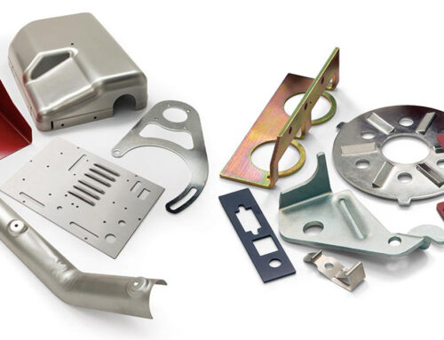
Sheet metal fabrication is a manufacturing process that involves cutting, punching, stamping, and bending flat metal sheets into functional parts. Using 3D CAD models, machine code is generated to guide precision equipment in shaping the final component.
This method is ideal for both low-volume prototyping and high-volume production, thanks to its strength, repeatability, and cost-efficiency—especially once initial tooling and setup are complete. Because all parts are formed from a single sheet, designs must maintain consistent thickness throughout. Following proper design guidelines and tolerances is essential to achieve accurate, high-quality results.
Designing for sheet metal fabrication requires a balance of functionality, manufacturability, and cost-efficiency. Before diving into specific features and tolerances, it’s important to understand how material choice, thickness, and part size can affect the final outcome. This section lays the foundation for making smart design decisions from the start.
1.1 Size Considerations
When designing sheet metal parts, it’s important to account for both the minimum and maximum size limits that can be reliably manufactured. These constraints vary depending on whether the part is flat or formed. The table below outlines the typical size limits for sheet metal fabrication, including the smallest feasible part sizes and the maximum bendable length.
| Part Type | Dimension Type | Inches | Millimeters |
| Flat Part | Minimum Size | 0.250 in. × 0.250 in. | 6.35 mm × 6.35 mm |
| Formed Part | Minimum Size | 0.500 in. × 0.500 in. | 12.7 mm × 12.7 mm |
| All Part Types | Maximum Overall Size | 39 in. × 47 in. | 990.6 mm × 1,193.8 mm |
| All Part Types | Maximum Bend Length | 47 in. | 1,193.8 mm |
1.2 Sheet Metal Materials & Thickness

Below is a table showing typical thickness ranges for different materials.
But Note that a common trend is negative tolerance, meaning finished parts may be slightly smaller than the design size. This should be considered to ensure product quality.
| Steel | Stainless | Aluminum | Copper | Brass | ||||||
|---|---|---|---|---|---|---|---|---|---|---|
| CRS/HRPO* | Galvanneal | Galvanized | 304-2B | 304-#4 | 316-2B | 5052-H32 | 6061-T6 | C101 | C110 | C260 |
| 0.024 | 0.028 | 0.028 | 0.024 | 0.024 | 0.024 | 0.025 | 0.025 | 0.025 | 0.025 | |
| 0.030 | 0.034 | 0.034 | 0.029 | 0.029 | 0.029 | 0.032 | 0.032 | 0.032 | 0.032 | 0.032 |
| 0.036 | 0.040 | 0.040 | 0.036 | 0.036 | 0.036 | |||||
| 0.042 | 0.040 | 0.040 | 0.040 | 0.040 | 0.040 | |||||
| 0.048 | 0.052 | 0.052 | 0.048 | 0.048 | 0.048 | 0.050 | 0.050 | 0.050 | 0.050 | 0.050 |
| 0.060 | 0.063 | 0.063 | 0.060 | 0.060 | 0.060 | 0.063 | 0.063 | 0.064 | 0.062 | 0.063 |
| 0.075 | 0.079 | 0.079 | 0.075 | 0.075 | 0.075 | 0.080 | 0.080 | 0.080 | 0.080 | 0.080 |
| 0.090 | 0.093 | 0.093 | 0.090 | 0.090 | 0.090 | 0.090 | 0.090 | 0.093 | 0.093 | 0.093 |
| 0.105 | 0.108 | 0.108 | 0.105 | 0.105 | 0.105 | 0.100 | 0.100 | |||
| 0.120 | 0.123 | 0.123 | 0.120 | 0.120 | 0.120 | 0.125 | 0.125 | 0.125 | 0.125 | 0.125 |
| 0.135* | 0.138 | 0.138 | 0.135 | 0.134 | 0.135 | |||||
| 0.164* | 0.165 | 0.160 | 0.160 | |||||||
| 0.179* | 0.187 | 0.190 | 0.190 | |||||||
| 0.239* | 0.250 | 0.250 | 0.250 | |||||||
*These thicknesses are available as Hot Rolled, Pickled & Oiled (HRPO) only
2. General Tolerances
| Feature | Tolerance (US) | Tolerance (Metric) | Feature | Tolerance (US) | Tolerance (Metric) |
| Bends | ±1° | ±1° | Forming | ±0.020 in. | ±0.508 mm |
| Angularity | ±1° | ±1° | Offsets | ±0.020 in. | ±0.508 mm |
| Hole Diameters | ±0.005 in. | ±0.127 mm | Diameters with Inserts | ±0.003 in | ±0.0762 mm |
| Holes | ±0.005 in. | ±0.127 mm | Edge to Edge | ±0.005 in. | ±0.127 mm |
| Edge to Hole | ±0.005 in. | ±0.127 mm | Hole to Hole | ±0.005 in. | ±0.127 mm |
| Hole to Hardware | ±0.010 in. | ±0.254 mm | Edge to Hardware | ±0.010 in. | ±0.254 mm |
| Hardware to Edge | ±0.010 in. | ±0.254 mm | Bend to Hole | ±0.015 in. | ±0.381 mm |
| Hardware to Hardware | ±0.015 in. | ±0.381 mm | Bend to Hardware | ±0.015 in. | ±0.381 mm |
| Bend to Edge | ±0.010 in. | ±0.254 mm | Bend to Bend | ±0.015 in. | ±0.381 mm |
| Bend to Feature | ±0.010 in. | ±0.254 mm | Features Separated by 2+ Bends | ±0.030 in. | ±0.762 mm |
| Linear Dimensions (Excl. to Bend) | ±0.004 in. | ±0.1 mm | Surface Roughness | / | ±3.2 μm |
But please note that this table simply shows general tolerances for standard sheet metal fabrication; for special custom requirements, please contact our team.
3. Design Guidelines for Bending
3.1 Critical Dimensions
Bend Line: The straight line marking where the flat section ends and the bend begins on the sheet’s surface.
Bend Radius: The distance from the bend axis to the inside surface of the material. It defines the curvature between the bend lines.
Bend Angle: The angle formed during bending, measured between the bent flange and its original flat position. The outside bend radius equals the inside radius plus material thickness.
Neutral Axis: The internal layer of the sheet that does not stretch or compress during bending—it stays the same length.
K-Factor: The ratio of the distance from the neutral axis to the material thickness (T/t). It typically ranges from 0.25 to 0.50 and varies with material type, bend method, and angle.
Bend Allowance: The arc length of the neutral axis within the bend area. It’s used to calculate the flat pattern length before bending.
*Here are some common K-factor values you can use as general design references.
| Bending Method | Radius Range | Aluminum (Soft) | Aluminum (Hard) | Stainless Steel |
| Air Bending | 0 – 1× Thickness | 0.33 | 0.38 | 0.40 |
| 1× – 3× Thickness | 0.40 | 0.43 | 0.45 | |
| >3× Thickness | 0.50 | 0.50 | 0.50 | |
| Bottom Bending | 0 – 1× Thickness | 0.42 | 0.44 | 0.46 |
| 1× – 3× Thickness | 0.46 | 0.47 | 0.48 | |
| >3× Thickness | 0.50 | 0.50 | 0.50 |
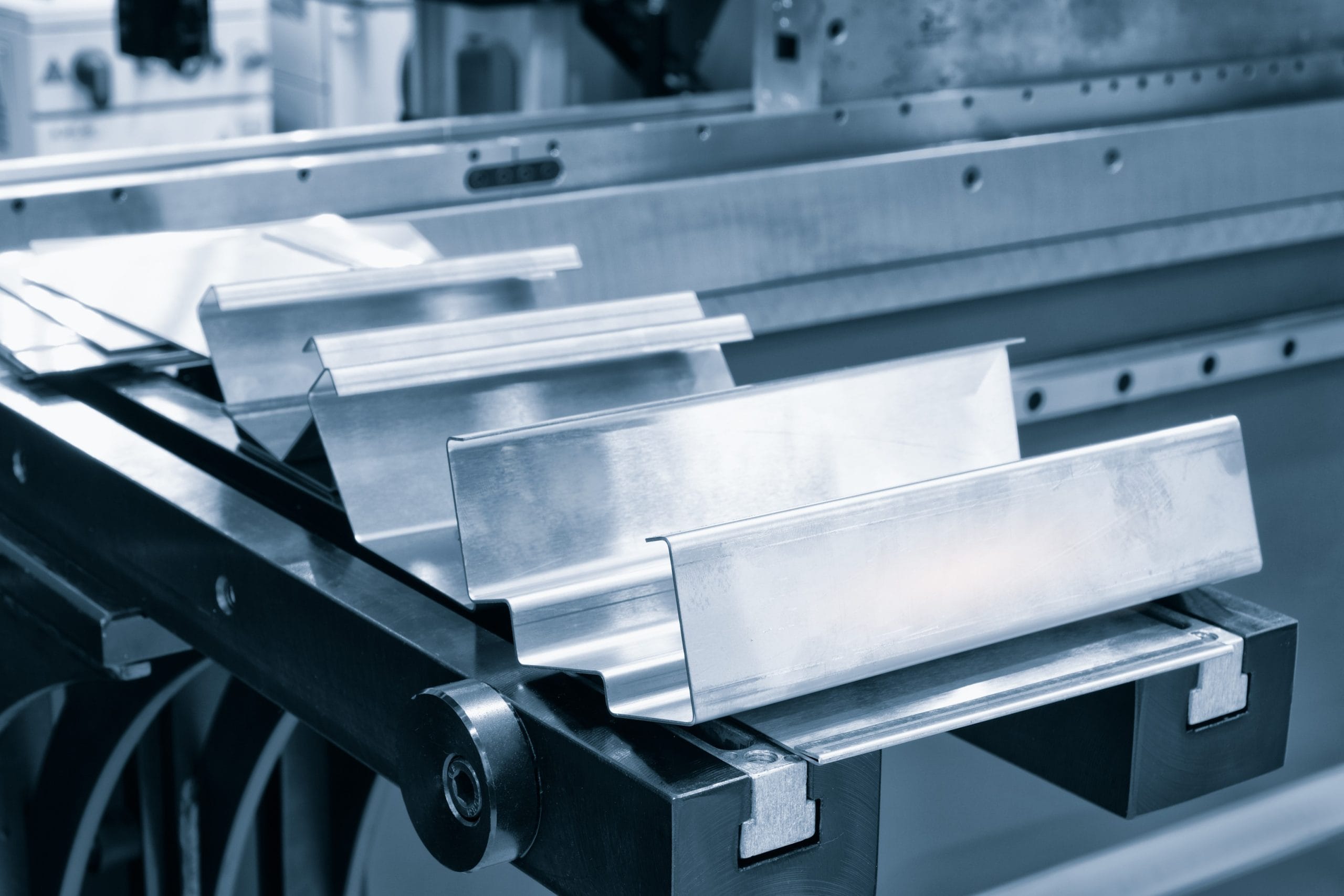
3.2 Brake Lines
Brake lines are a common result of the force applied to sheet metal during the bending process, typically performed using a press brake. These lines are inherent to the manufacturing process and will remain on the final product unless additional treatments are applied.
To remove these brake lines, a direct oscillating sanding machine can be used. For parts requiring specific aesthetic qualities or a cosmetic finish, several secondary processing options are available:
- Using a direct oscillating (DA) tool to blend the brake line into the surrounding material.
- Placing a rubber slip sheet on top of the die tooling during the bending process.
- Applying a finish, such as powder coating, after forming to cover the entire surface of the part.
Note: Plating thickness is often not sufficient to cover brake lines, so these lines may still be visible after plating.
If your part requires a uniform finish with no visible brake lines, please contact our applications engineers to explore the best method for your specific needs.
(Click to Enlarge)
Bent sheet metal showing visible press brake lines.
(Click to Enlarge)
A direct oscillating sanding tool can effectively eliminate brake lines.
3.3 Bend Radius
We maintain a tolerance of +/- 1 degree on all bend angles and offer a variety of common bend radii. Our standard options include 0.030 inches (0.762 mm), 0.060 inches (1.524 mm), 0.090 inches (2.286 mm), and 0.120 inches (3.048 mm), with tooling available on a 3-day lead time. For optimal results, it is advised to use consistent radii across all bends. Additionally, the minimum flange length for sheet metal parts must be at least four times the material thickness.

3.4 Minimum Flange Lengths

To ensure an accurate bend in a press brake, the design must make three (3) points of contact with the machine. The image to the right highlights these crucial points of contact.
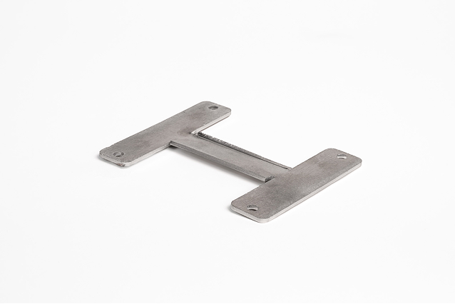
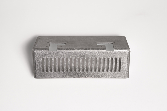
If only two points of contact are made, the final part may experience a deformed flange. For example, in the image below, the “H” bracket’s center portion has two flanges on the z-axis, which didn’t make three points of contact during the bending process. This resulted in inconsistent and deformed bends.
(Click to Enlarge)
The center portion of this “H” bracket demonstrates quality issues due to insufficient material on the z-axis flanges, leading to bending inconsistencies.
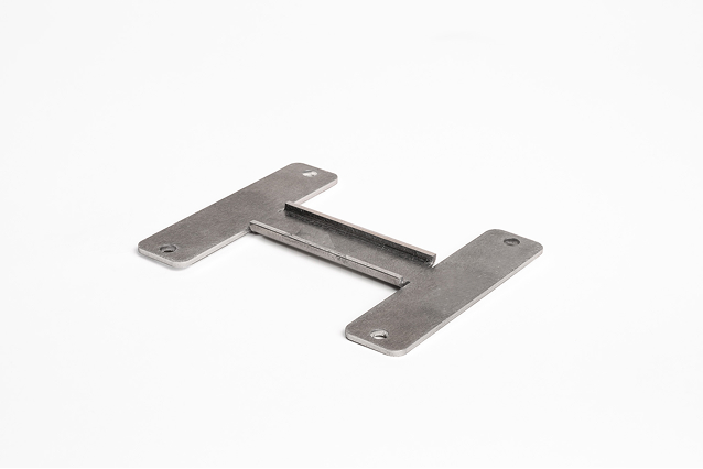
(Click to Enlarge)
By adding material to a short flange, the workpiece can make three points of contact with the press brake, ensuring consistent and accurate bending.
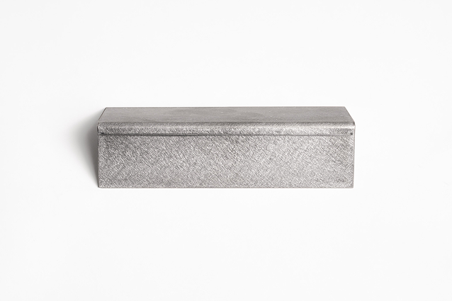
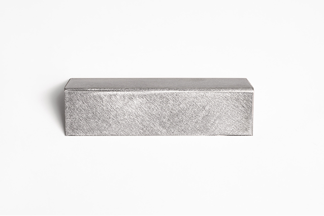
3.5 Offsets and Hems

Hems are used in sheet metal design to fold an edge back onto itself, improving edge safety, enhancing aesthetics, and reinforcing structural strength. They help eliminate sharp edges, hide burrs, and provide added stiffness to the part—though they may slightly increase weight.

There are three common types of hems:
Open Hems
- Inside Diameter: At least equal to the material thickness
- Return Flange Length: Minimum of 4 × material thickness
- Note: Larger diameters may lose roundness, especially in thinner materials
Closed Hems
- Inside Diameter: Also equal to material thickness
- Return Flange Length: Minimum of 6 × material thickness
- Use Case: Often applied at part ends to create a clean, rounded finish
Teardrop Hems
- Inside Diameter: Equal to material thickness
- Opening: Should be at least ¼ of material thickness
- Return Flange Length: Minimum of 4 × material thickness
- Advantage: Reduces risk of material cracking compared to flat hems
Flat hems are generally discouraged, as they can cause material fractures. Teardrop or open hems are preferred for maintaining strength and form.
The table below provides the minimum distance requirements between hems and nearby features like holes and bends. These values help maintain structural integrity and ensure proper part performance during fabrication.
| Feature Relationship | Minimum Recommended Distance |
| Hem to Hole | At least 2 × material thickness + hem radius |
| Hem to Internal Bend | At least 5 × material thickness |
| Hem to External Bend | At least 8 × material thickness |
4. Designing Effective Features
4.1 Feature Proximity Rules
When sheet metal is bent in a press brake, the material naturally stretches along and near the bend line. Any feature located within a certain proximity of the bend—usually within 4 times the material thickness from the bend—is at risk of deformation.
However, there are several design strategies that can mitigate this issue and help you achieve your intended design outcome. Below are common design solutions for addressing this challenge:
| Possible Solutions | Rationale for Using this Solution |
| Allow the feature to deform during bending | This solution is only recommended if deformation is acceptable, such as in cases where the feature’s criticality is low or during early prototyping. Future design changes can resolve the issue. Protolabs’ design for manufacturability analysis may suggest feature deformation as a viable option. Before manufacturing begins, our sheet metal fabrication experts will evaluate all potential deformation scenarios and contact you if any concerns arise. |
| Change the bend radius | Choose smaller internal bend radiuses if features are close to, but not directly through, the bend can reduce material stretching at the bend. A smaller bend radius helps to minimize deformation risks. Consult our list of available internal bend radii to choose the best option for your design. |
| Re-locate/move the at-risk feature | The most common solution when dimensional accuracy of the feature is essential. This approach involves repositioning the feature to a location where it is less prone to deformation. Our design for manufacturability toolkit provides a reference guide that outlines minimum feature distances based on material type and thickness, helping avoid distortion issues. |
In most cases, these design solutions do not significantly affect the cost or lead time of your project, but they can help avoid additional processing costs over the lifespan of your part.
Not sure which solution is best for your design? Our sheet metal experts are available to offer a free 30-minute design review, with same-day appointments available!
4.2 Extending Features
When sheet metal is bent in a press brake, the material naturally stretches along and near the bend line. Any feature located within a certain proximity of the bend—usually within 4 times the material thickness from the bend—is at risk of deformation.
However, there are several design strategies that can mitigate this issue and help you achieve your intended design outcome. Below are common design solutions for addressing this challenge:
| Possible Solutions | Rationale for Using this Solution |
| Allow the feature to deform during bending | This solution is only recommended if deformation is acceptable, such as in cases where the feature’s criticality is low or during early prototyping. Future design changes can resolve the issue. Protolabs’ design for manufacturability analysis may suggest feature deformation as a viable option. Before manufacturing begins, our sheet metal fabrication experts will evaluate all potential deformation scenarios and contact you if any concerns arise. |
| Change the bend radius | Choose smaller internal bend radiuses if features are close to, but not directly through, the bend can reduce material stretching at the bend. A smaller bend radius helps to minimize deformation risks. Consult our list of available internal bend radii to choose the best option for your design. |
| Re-locate/move the at-risk feature | The most common solution when dimensional accuracy of the feature is essential. This approach involves repositioning the feature to a location where it is less prone to deformation. Our design for manufacturability toolkit provides a reference guide that outlines minimum feature distances based on material type and thickness, helping avoid distortion issues. |
In most cases, these design solutions do not significantly affect the cost or lead time of your project, but they can help avoid additional processing costs over the lifespan of your part.
Not sure which solution is best for your design? Our sheet metal experts are available to offer a free 30-minute design review, with same-day appointments available!
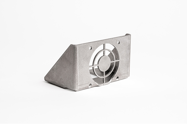
(Click to Enlarge)
When features, such as the fan bracket and bottom holes, are too close to a bend, the sheet metal will experience deformation during the bending process.
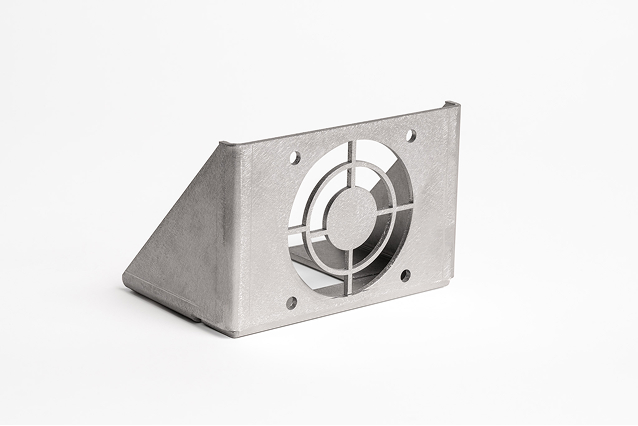
(Click to Enlarge)
In this case, reducing the size of the internal bend radius effectively provided the extra material needed, preventing deformation of the fan cutout and holes.
One more option to prevent deformation along bends is to extend a feature through the bend.
In images A and B (below), the bracket has two L-shaped cutouts that terminate at the bend. The material experiences deformation where the top of each L intersects with the bend.
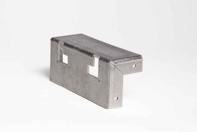
(Click to Enlarge)
image A
(Click to Enlarge)
image B
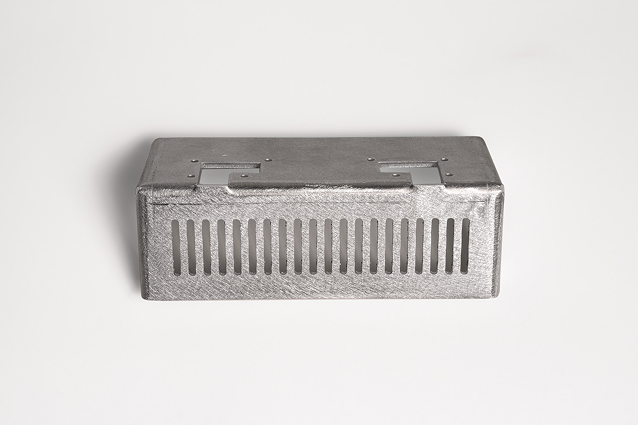
By following the feature distance guidelines, deformation can be eliminated by extending the L-shape through the bend line. This method removes the material where the bend would typically occur, as demonstrated in images C and D below.
(Click to Enlarge)
image C
(Click to Enlarge)
image D
4.3 Holes and Slots
Always keep hole and slot diameters at least equal to the material thickness. For high-strength materials, increase the diameter to reduce the risk of distortion or tearing during forming.

Holes and slots should have a minimum diameter equal to the material thickness. For materials 0.036 inches (0.914 mm) or thinner, holes should be at least 0.062 inches (1.574 mm) from the material edge. For thicker materials, the minimum distance increases to 0.125 inches (3.175 mm) to prevent distortion. If hardware inserts are needed, spacing should follow the manufacturer’s specifications.
Recommended Clearances
To maintain part integrity and avoid deformation:
- Distance from Bend:
- Place holes at least 5 × material thickness + bend radius from any bend.
- Place slots at least 4 × material thickness + bend radius from a bend.
- Distance from Edges:
- Keep holes and slots at least 2 × material thickness away from any edge to prevent bulging.
- Distance Between Holes:
- Maintain a spacing of at least 6 × material thickness between holes for optimal strength and formability.
4.4 Notches and Tabs
Notches and tabs are essential features used to create clearance between components, improve tool access, and support assembly processes. A notch removes material from the edge, while a tab is a protruding section typically used for alignment, bending, or fastening. Notches should be at least the material thickness or 0.04 inches (1.016 mm), whichever is greater, and their length must not exceed five times their width. Tabs must measure at least twice the material thickness or 0.126 inches (3.200 mm), whichever is greater, with a maximum length of five times their width as organized below.

Notch Guidelines
- Minimum width: 1 mm or equal to material thickness, whichever is greater
- Maximum length (straight or radius end): 5 × material thickness
- V-notch length: No more than 2 × width
- Corner radius: At least 5 × material thickness
Tab Guidelines
- Minimum width: 2 mm or 2 × material thickness, whichever is greater
- Maximum depth: 5 × tab width to maintain strength and manufacturability
4.5 Countersinks and Counterbores
Countersinks and counterbores are commonly used to create flush surfaces for fasteners, enhancing both appearance and functionality in sheet metals.
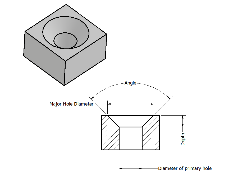
Countersinks
These are conical recesses designed to allow screws to sit flush with or below the surface after assembly. They’re ideal for applications requiring a smooth, snag-free exterior.
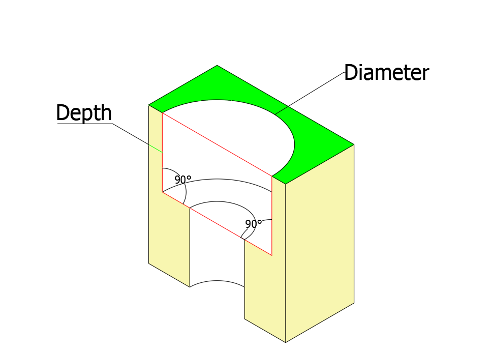
Counterbores
These are flat-bottomed holes designed to fit bolts or nuts, allowing their heads to be recessed. However, counterbores are not recommended for thin materials, as they may weaken the part.
Key Design Guidelines
• Countersink depth should be no more than 0.6 × material thickness
• Ensure at least 50% contact between fastener and countersink for a secure fit
Minimum Distance Requirements
| Feature Type | Minimum Distance Guideline |
| Between countersink and edge | ±4 × material thickness |
| Between countersink and bend | ±3 × material thickness |
| Between two countersinks | ±8 × material thickness |
| Between counterbore and edge | ±4 × material thickness |
| Between counterbore and bend | ±4 × material thickness + bend radius |
| Between two counterbores | ±8 × material thickness |
5. Finishing and Post-Processing Options
Here are some common post-processing options for sheet metal parts. We have organized the content into a table for your reference. More details about hardware inserts and surface finishing come after these tables.
")
Hardware Inserts
Including hardware inserts in your sheet metal design is an effective and affordable solution for joining components. However, when placing hardware holes and inserts near bend lines, it is crucial to account for potential deformation during the bending process.
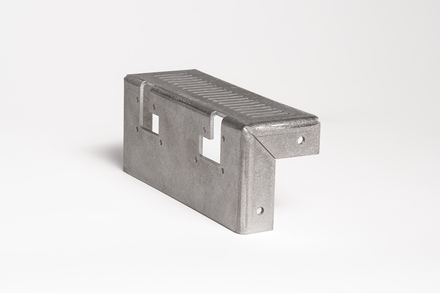
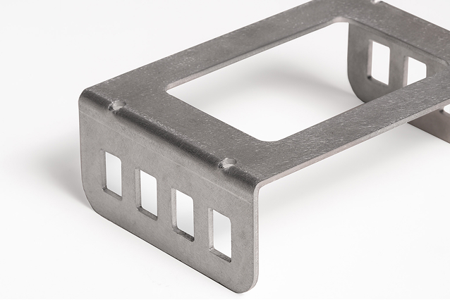
If hardware holes are too close to a bend, the material will stretch, which may impact the integrity and functionality of the insert. The mounting bracket below demonstrates how the bending process can influence hardware positioning and installation.
To overcome this challenge, a recommended approach is to adjust the design by moving hardware holes further from the bend line or considering alternative insertion methods that ensure secure functionality even in challenging bending scenarios. This proactive design strategy can help avoid deformation and maintain the effectiveness of hardware inserts.
(Click to Enlarge)
This mounting bracket has laser-cut holes along the bend line, causing the holes to become oblong (non-round) after forming.
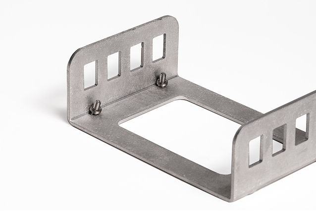
(Click to Enlarge)
As a result, the hardware inserts won’t properly seat into the holes, preventing them from gripping the component material and impacting the functionality of the insert and the overall design.
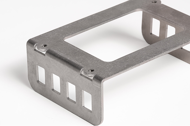
The term “relief” is commonly used in sheet metal manufacturing, especially in the context of “bend relief,” but it can also apply to other design situations. Relieving sheet metal involves strategically placing cut-outs to enable material stretching during bending, preventing distortion of critical features.
(Click to Enlarge)
(Click to Enlarge)
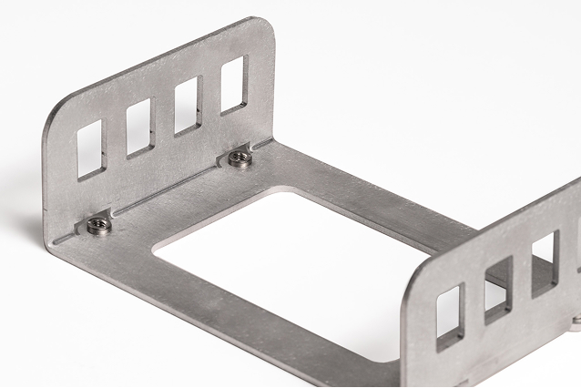
For hardware holes near bends, adding cutouts around the hole allows for material relief during bending, preventing distortion. This approach helps maintain the design intent while keeping costs low.
Considering material relief during the design phase offers several benefits, such as:
6. KingStar Mold’s Capabilities and Support
KingStar Mold is a leading provider of custom manufacturing solutions, specializing in the production of high-quality plastic and metal parts. The company offers a wide range of services, including injection molding, CNC machining, 3D printing, and sheet metal fabrication. Below is a detailed overview of the company’s capabilities and the specific equipment and technologies it utilizes.
6.1 Our Equipment and Capabilities of Sheet Metal Fabrication
KingStar Mold provides a comprehensive range of sheet metal fabrication services, including:
- Laser Cutting: Our company uses advanced laser cutting machines to achieve high precision and efficiency in cutting metal sheets. These machines are capable of handling complex shapes and are ideal for applications requiring tight tolerances, such as aerospace and automotive components.
- Brand and Model: Trumpf, Büchi, and Canon laser cutting machines .
- Specs: Cutting accuracy of ±0.05mm, suitable for materials up to 6mm thick.
- Punching and Forming: KingStar Mold employs intricate punch presses and forming machines to create precise holes and shapes in metal sheets, which is particularly useful for creating structural components and assemblies, and capable of handling sheet thicknesses from 0.5mm to 6mm.
- Bending and Folding: Our company uses Hobart, KUKA, and CNC Press Brake hydraulic and CNC bending machines to fold and shape metal sheets into the desired form. This is essential for creating complex geometries and ensuring structural integrity, with bending accuracy of ±0.1mm, suitable for sheet thicknesses up to 4mm.
- Welding and Assembly: KingStar Mold offers welding services using arc welding machines, such as the WSM315D model, to join metal parts and create robust assemblies, suitable for welding up to 10mm thick steel.
- Surface Finishing: Our company provide surface treatment services, including anodizing, electroplating, PVD coating, and sandblasting, to enhance the appearance and durability of metal parts.
6.2 Applicable Industries and Use Cases
- Aerospace: For manufacturing aircraft components, fuselage parts, and structural frames.
- Automotive: For producing body panels, chassis parts, and interior components.
- Electronics: For creating enclosures, brackets, and connectors.
- Medical Devices: For manufacturing surgical tools, diagnostic equipment, and patient care devices.
- Construction and Architecture: For producing building facades, partitions, annd decorative elements.
6.3 Support and Additional Services
In addition to its core fabrication capabilities, KingStar Mold offers a wide range of support services from design review to product delivery, to ensure customer satisfaction and project success:
- Design Assistance: The company provides Design for Manufacturing (DFM) support to help clients optimize their designs for efficient production.
- Rapid Prototyping: Using 3D printing and CNC machining, KingStar Mold can produce prototypes quickly, allowing clients to test and refine their designs before full-scale production.
- Custom Tooling and Dies: The company offers custom tooling and die solutions for specialized applications, ensuring that each part meets the required specifications.
- Quality Control: KingStar Mold adheres to strict quality control standards, including ISO 9001 certification, to ensure that all fabricated parts meet the highest quality requirements.
- Logistical Support: The company provides end-to-end logistics support, including mold storage, maintenance, and repair services, to ensure smooth production cycles.
Just like all designs, the design of sheet metal parts also needs to follow DFM in order to achieve the most efficient production and avoid wasting your time and money. This article elaborates on some key design points for sheet metal parts. By adhering to these points, you can ensure the cost-effectiveness of your investment and ensure the achievement of high-quality and repeatable results. Whether you are conducting prototype design or preparing for large-scale production, if these principles can be applied at the design stage as early as possible, it will significantly reduce rework, delays, and the overall cost of the project.
For complex or custom sheet metal components, our team at KingStar Mold is always ready to assist with design reviews, manufacturability feedback, and optimized fabrication solutions tailored to your application.
")