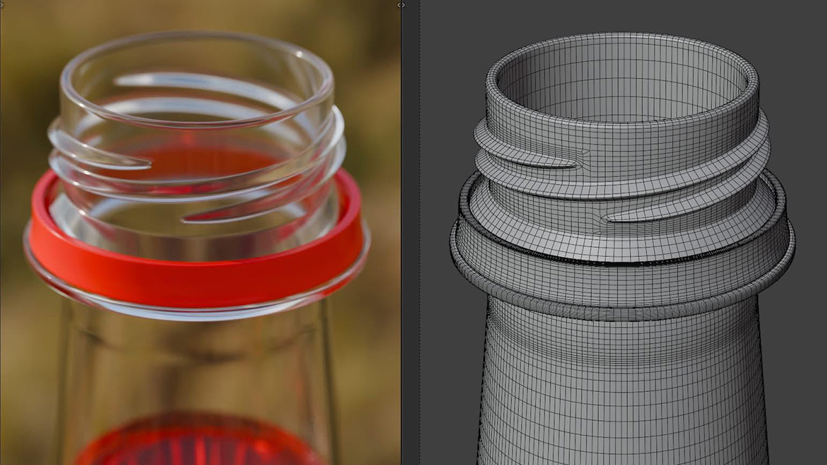
Have you ever wondered why the threads on the plastic bottle necks are on the outside instead of the inside, though the functions would be exactly the same? Many products have been designed with various appearances for innovation. Take plastic bottles here for example. In terms of shape, there are thick ones, thin ones, round ones, and even square ones. In terms of cover, there are transparent ones, semi-transparent ones, matte ones, and various colors. However, in terms of the threads, almost all manufacturers seem to have agreed on this, that the threads on all bottles should be located on the outside. But why? Keep reading, and this article will solve your doubts.
As I mentioned before, as long as there is a thread, we can rotate the bottle cap off. Functionally, there is no difference whether it’s inside or outside. Thus it is unlikely that this pattern is specifically designed function-wise. So this brings us to the topic of manufacturing. Is it possible that it’s due to production limitations?
First of all, we need to understand that when manufacturing plastic bottles in large quantities, as a custom plastic part injection molding company, we can tell you that the most commonly used production methods to reduce costs are injection molding or blow molding. As for blow molding, just like injection molding, it also requires a mold, but instead of injection, it uses air to blow the plastic into shape. The shapes of the products produced by these two methods are closely related to the molds and machines.

Figure 1 Structure of Bottle Cap
The height is approximately 75 mm; there are 2 handles on the outer surface, and the maximum distance between the two handles is 127 mm; the main part of the bottle cap is in a circular shape(outer diameter φ66 mm); its inner surface has 2 rings of internal threads, with the specification of the internal threads being M58 mm; the length of the inner cylindrical surface of the bottle cap is 14 mm, and the length of the internal threads is 6 mm. The molding material is ABS. Because ABS is a relatively rigid material, the internal threads of the bottle cap must be removed by unscrewing rather than by force, as forced demolding could cause damage.
Since the examples here are produced by injection molding, we will now explain this issue by describing the injection mold and the injection process.
2. Mold Design
The mold is designed with 1-mold-2-cavity and three-plates. The outer shape of the plastic component is molded by the coordinated movement of two sliding cores, while its internal threading is produced using a dedicated threaded core insert. As shown in Figure 2.
Figure 2 Structure of Injection Mold (part)
Due to the small ejection distance of the slide core sliders, it is driven by a slanted guide pillar. The inner hole of the plastic part is formed using a structure where the fixed core and the moving core meet.
2.1 Core Structure
The structure of the plastic part determines that the mold must be demolded first with an internal thread, then the two slide core sliders are separated, and the gate is set on the inner cylindrical surface of the plastic part to be molded. The core is divided into two layers: the inner layer and the outer layer. On the inner layer core, the runner, gate, push rod and draw pin are set, while on the outer layer core, the structure for forming the internal thread of the plastic part is set. The structure of core is shown in Figure 3.

figure 3 Structure of Mold Core
2.2 Gating System
Each plastic part to be molded is provided with one straight runner, aligning the pinpoint gate with the parting surface where the fixed core and moving core of the inner hole of the molded part meet. A flow channel is then machined on the end face of the moving core, and the material is fed through an edge gate. Each plastic part has two gates, as shown in Figure 4.

figure 4 Structure of Gating System
This gating design has two advantages:
① The gate is relatively concealed, which does not affect the appearance of the molded part.
② It allows automatic trimming of the gate solidified material.
To prevent weld lines on the molded part, the flow channel on the end face of the moving core is slightly extended at both ends to serve as a cold material reservoir.
2.3 Transmission Mechanism
A transmission system was developed to allow the threaded core to rotate automatically. This system includes a hydraulic cylinder, a rack-and-pinion assembly, a driven gear, a threaded nut, and a tapered roller bearing, as illustrated in Figure 5.

figure 5 Structure of Transmission Gear
Notes
1. Hydraulic cylinder; 2. Rack; 3. Pinion gear (gear meshing with the rack); 4. Bronze bushing; 5. Driven gear; 6. Nut; 7. Inner core; 8. Driving gear; 9. Gear adjustment device
A gear adjustment unit is built into the threaded nut mechanism to simplify alignment of the threaded core during mold assembly. Additionally, a tapered roller bearing is mounted beneath the driving gear to support its rotation. Two cores are driven by the same driving gear.
When the threaded core rotates, it simultaneously moves axially under the drive of the threaded nut mechanism, allowing the inner threads of the molded plastic part to be demolded.
To extend the service life of the threaded core and prevent wear, a bronze bushing is installed on the outer cylindrical surface of the threaded core. The outer core consists of three parts: the top part forms the thread structure of the molded part; the middle part carries the driven gear; and the rear part contains the threads for the threaded nut mechanism. The nut in the threaded nut mechanism is fixed to the mold base plate.
2.4 Ejection Mechanism
Since the inner thread demolding mechanism operates before mold opening, after the inner thread is demolded, the plastic part still adheres to the core and needs to be ejected by ejector pins. Six ejector pins are installed on the inner core. The structure of the ejection mechanism is shown in Figure 6.

figure 6 Structure of Ejection System
2.5 Cooling System Design
The inner core of the mold is a cylindrical shaft. To achieve better cooling performance, two straight-through cooling channels are machined into the inner core, which are connected to water pipe fittings through the mold plates, as shown in Figure 7(a).
Each slide core slider contains two cavities. To ensure consistent cooling for both cavities, two independent cooling channels are designed on each slider. Each cooling channel consists of multiple straight-through passages arranged in a complex 3D zigzag layout, as illustrated in Figure 7(b).

figure 7 Cooling System
The cooling channel design for the fixed mold plate is relatively simple thus we won’t describe it further here.
2.6 Mold Structure
Since the mold is a single mold with two cavities, material is fed through edge gates, using a three-plate mold base.
To install the transmission mechanism composed of a hydraulic cylinder, rack and pinion, driven gear, threaded core, and tapered roller bearing, a non-standard mold base is used. To accommodate the transmission mechanism, three extra plates—the gear support plate, core holder plate, and backing plate—are integrated between the moving platen and the spacer block on the existing mold base, as illustrated in Figure 8.

figure 8 Structure of Injection Mold
As shown in Figure 9, the molded part’s core consists of two layers: an inner and an outer core. During demolding, the outer core simultaneously rotates and moves axially. Therefore, a clearance must be maintained between the outer core and the core retainer plate, set at 16 mm. Similarly, a clearance should also be maintained between the driven gears and nuts on the two cores.

figure 9 Structure of Injection Mold – Illustration
Notes
1. Moving mold base plate, 2. Ejector plate, 3. Ejector pin retainer plate, 4. Spacer block, 5. Backing plate, 6. Core retainer plate, 7. Pull rod, 8. Gear mounting plate, 9. Tapered roller bearing, 10. Driving gear, 11. Rack, 12. Pinion gear (gear meshing with rack), 13. Outer core, 14. Bronze bushing, 15. Ejector pin, 16. Inner core, 17. Bronze bushing, 18. Angled guide post, 19. Fixed mold plate, 20. Fixed mold insert, 21. Stripper plate, 22. Fixed mold base plate, 23. Pull rod, 24. Positioning ring, 25. Half slider, 26. Moving mold plate, 27. Nut, 28. Gear adjustment device.
After injection molding is completed and before the moving mold and fixed mold open, the hydraulic cylinder drives the outer core 13 to rotate. Under the action of the threaded core mechanism, the outer core 13 rotates while moving axially, demolding from the molded part. Once the demolding action of the threaded drive mechanism stops, the mold begins to open. The mold opening process is divided into two steps:
The 1st step is the stripper plate 21 separating from the fixed mold plate 19 to remove the gate residue;
The 2nd step is the moving mold plate 26 separating from the fixed mold plate 19. During this second step, the angled guide post 18 drives the half slider 25 to perform the demolding motion.
After the injection machine’s slider stops moving with the moving mold, the injection machine’s ejector rod drives hte mold’s ejection mechanism (ejector plate 2, ejector pin retainer plate 3, pull rod 7, and ejector pin 15) to push out the molded part. After removing the part, the injection machine’s slider drives the moving mold section of the mold to reset. The reset process is the reverse of the mold opening process. Once the mold is fully reset, production of the next part can begin.
So why is the outer thread the go-to choice for bottle mouths? It all comes down to the molding process and the mold structure behind the scenes. Using an outer threaded core simplifies the demolding step, making it easier to rotate and pull the part off without damaging the delicate threads inside. This design not only improves production efficiency but also extends the mold’s service life and reduces manufacturing costs. In short, manufacturers use outer threads not because they’re following the crowd or avoiding innovation, but because it’s what production demands.
Want to find a one-stop manufacturer for your custom design bottle caps? Contact us now! Write to sales@kingstarmold.com or leave an online message, you will get response via email within 24 hours.