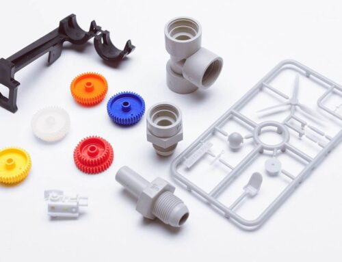
Two-shot injection molding technology is widely used in fields such as electronics, automotive parts, medical equipment, household goods, etc., due to its advantages of achieving dual color/multi-color integration of products, composite of soft and hard materials, and integration of function and appearance. For example, our daily use of mobile phone cases (hard plastic substrate+soft anti-slip edges), car interior buttons (main hard plastic body+tactile soft plastic), and children’s toys (colorful splicing+safety soft components) all rely on the precise support of two-shot injection molds.
1. Material and Molding Priority: Hard plastic is made once, soft plastic is made twice (soft plastic is prone to deformation, and later molding can avoid damage); Make transparent material once and non transparent material twice (to protect the transparency of transparent parts and avoid scratches during secondary molding); Make the plastic with high molding temperature once and the plastic with low molding temperature twice (to prevent high temperature from affecting the already formed parts).
2. Optimal Sealing Method: Try to use a sealing method that relies on breaking the seal to avoid inserting and breaking the seal. If the product structure makes it infeasible to insert and break the sealing adhesive, it is recommended to communicate with the customer to modify the product design. Breaking the sealing adhesive can improve the sealing effect and reduce the risk of defects.
3. Mold Base Structure Requirements: Guide pins and bushings must be symmetrical in all directions, and the front and rear molds must be symmetrical; The rear mold needs to be able to rotate 180°while the front mold remains fixed, which is the core structural foundation of the rotating two-shot molds.
4. Product and Equipment Compatibility: Product spacing should base on nozzles spacing of injection machine. The nozzle spacing of domestic two-shot injection molding machines is often not adjustable, while some foreign models can be adjusted; If the distance between the ejector pin holes and the injection molding machine nozzle does not match, they should be made into elongated slots for adaptation.
5. Ejection System Design: Two independent ejection systems are required, with two ejector rods; The two products in the rear mold are the same, and the layout of the ejector pin is in a rotational relationship, not a translational one; The top pin plate can only be reset with a spring, and it is forbidden to force the screw to reset (to avoid affecting the rotation of the rear mold).
6. Interlocks and Positioning: Interlocks needs to be installed on the four sides of the mold center, and the front and rear molds should be symmetrical, otherwise the rear mold cannot be accurately aligned with the front mold after rotating 180°; The bottom plate of the rear mold needs to be designed with 2 positioning rings to ensure the accuracy of mold clamping.

7. Cooling Channel Layout Specifications: Inlet and outlet of cooling channels must be on the top/bottom (sky/earth) sides, and each circulating water inlet and outlet must be on the same plane. Ensure normal water line connection after rear mold rotation 180°. The size of the mold base should not exceed the height of the injection molding machine’s water connection slots, or cooling line connection will be impossible.
8. Cavity Layout and Operational Convenience: The first injection molded part should be put on the non operating side. When rotating 180°for the second injection molding, the product should rotate exactly to the operating side for easy removal; The code module position of the export mold needs to be on the operating side and non operating side, not on the ground side, to meet the requirements of fully automated production.
9. Parting Line Design: The parting line of the rear mold should be based on the contour of the two products. The parting line of the front mold can take the contour of a single product, and cannot use the combined product parting line to avoid affecting the forming accuracy.
10. Key Dimensional Tolerances:
- Front/Rear Flange Tolerance: -0.05mm; distance between two flanges: ±0.02mm;
- Single-Side Clearance Between Ejector Rod and Hole: 0.1mm;
- Center Distance Tolerance for Front/Rear Guide Pins/Bushings: ±0.01mm; mold frame sides and depth require added tolerances, e.g., frame depth tolerance: -0.02mm, to avoid flash due to height mismatch after rotation.
11. Mold Base Processing Benchmark: If the mold base manufacturer has completed the base, the distance center between the four guide pin/bushing holes should be taken as the benchmark for subsequent processing of the nozzle and ejector rod holes to prevent excessive deviation from causing the mold to get stuck; When customizing the mold base, it is necessary to clearly label it as “two-shot mold base”, requiring four guide pins/bushings, and frames to be symmetrical. After rotating the rear mold 180°, it can perfectly match the front mold.
12. Mold Thickness Requirements: The total thickness of the front mold panel and A-plate should not be less than 170mm. Before design, it is necessary to check the maximum and minimum mold thickness compatibility before design.
13. Gate Location Selection: For the first-shot products, latent injection molding is preferred to achieve automatic separation between the product and the gates; When it is not possible, three plate molds or hot runner molds can be considered; If a sprue is used for the first batch of material, a ripple should be designed to prevent residual material from penetrating the second shot.

2. Key Points for Designing Different Types of Two-Shot Molds
2.1 Rear Rotary Two-Shot Mold
1. Core Structure: Two front mold cores are identical, and the rear mold rotates 180°to achieve the second shot; After injecting hard plastic on one side, it is necessary to ensure that the product does not fall off and the gate can automatically separate during the rotation process. Then, soft plastic should be injected.
2. Ejector Pin Arrangement: There is no need to arrange a ejector pin on one side of the injection molded hard plastic, only a ejector pin can be set on the soft plastic side of the mold core.
3. Shrinkage Control: If soft plastic completely encapsulates the hard plastic, only consider the shrinkage rate of the hard plastic; If the two are contour connected, set shrinkage separately for both materials.
2.2 Straight Barrel + 90° Barrel Two-Shot Mold
1. Structural Feature: One set of molds uses a straight barrel and a 90°barrel for injection, without the need for rotation, only requiring one mold core.
2. Separation Method: Separation of soft and hard plastic relies on sliders for sealing, simplifying the mold structure and suitable for specific product forms.
2.3 General Structural Requirements
1. Cavity and Core Design: The two shapes of cavity are different, forming two different products respectively; The two shapes of the core are completely identical.
2. Rotation Alignment Check: The front and rear molds must be completely aligned after rotating 180° around the center. This check action must be mandatory during the design phase to avoid mold alignment deviation.
3. Ejector Rod Holes and Pin Length: Minimum distance between ejector rod holes is 210mm; large molds may need more. Since machine ejector pins are often short, the mold needs lengthened ejector pins, extending about 150mm beyond the mold base bottom plate.
4. Sprue Depth Limit: Depth of the sprue on the front side shall not exceed 65mm; the distance from the top of the sprue on the upper side (large sprue) to the center of the mold base shall not be less than 150mm.

3. Key Considerations for Two-Shot Injection Molding Process
1. Second Shot Cavity Design: To avoid damage or abrasion of the first shot product, local clearance can be designed, but the strength of the sealing position needs to be carefully considered to prevent plastic deformation caused by excessive injection pressure and the formation of flash.
2. Product Size Adaptation: The size of the first shot product can be slightly larger, so that it can closely fit with another cavity during the second shot, improving the sealing effect.
3. Sequence of Slider and Lifter: Before the A and B plates close, it is necessary to ensure that the front mold slider or lifter will not reset and damage the product first. A linkage structure should be designed to ensure that the A and B plates close first, and then slider or lifter reset.
4. Cooling Balance: Cooling channel layout of the two cavities and core should be sufficient, balanced, and consistent to ensure uniform temperature of mold, improve product forming quality and stability.
5. Material Compatibility: Two-shot injection molding can use the same plastic of different materials, or two different materials of plastic. Commonly combination is hard plastics such as ABS and PC combined with TPE soft plastics, and the interface interaction, shrinkage rate difference, and processing parameter adaptability of the two materials need to be carefully considered; If the adhesion between two materials is poor, embossing or sealing grooves should be applied to the joint of the mold, and the material thickness should be designed reasonably.
6. Determination of Shrinkage Rate: Shrinkage rate of two-shot molds usually depends on the first-shot material, as it has already supported the structure of the plastic product. However, consider material flow, product shape, etc. Sometimes both materials need separate shrinkage rates.
7. Preventing Deformation During Second Shot: During the second injection molding, pay attention to whether the plastic flow will affect the already formed product, causing deformation. If this risk exists, improve it by optimizing the gate position, adjusting the injection pressure.
8. Plug & Shut-off Surface Requirements: The slope difference of all plug and shut-off surfaces must be greater than 0.1mm to improve fitting accuracy and reduce flash.
9. Specific Material Molding Sequence: When ABS/PC+ABS, ABS/PMMA, ABS/PC, combination two-shot injection molding, it is necessary to first inject PC, PMMA or PC+ABS with higher temperature; Transparent shell molds often adopt inverted mold structures to ensure the quality of transparent parts.

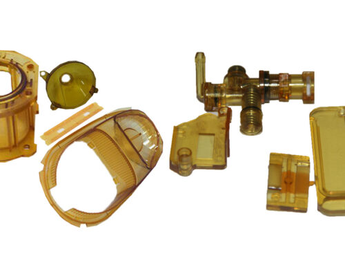
4. Special Requirements for Large Transparent Two-Shot Injection Molding
1. Gate Location Reservation: Confirm position of the gate in advance with the injection mold manufacturer to reach a consensus and avoid subsequent modifications affecting product molding.
2. Material Thickness: Recommended transparent materials thickness at least 0.8mm, while non transparent materials thickness at least 0.7mm; Non transparent materials should use light colors as much as possible. If the product has LED lights, consider light-locking design.
3. Structural Details: Width of the transparent component’s parting surface and holes should be consistent, with a recommended width of 0.5mm. The curved surface transition should be smooth to avoid excessive light transmission when viewed from the side, which may affect the appearance. The number of holes should be minimized as much as possible; The width of non transparent reinforcement bars should be controlled between 0.5-0.6mm to avoid shrinkage.
4. Process Limitations: Currently, it is not recommended to do two-shot injection molding with main lenses, as the mold and product costs are extremely high, and strict requirements are placed on the manufacturer’s equipment and technical level; If production is necessary, the manufacturer needs to provide a complete process solution and review key links one by one.
5. Reliability Testing: Large area two-shot injection molded parts need to pass drop testing and thermal shock testing (-40 ℃~65 ℃, lasting for 48 hours). During these two tests, transparent and non transparent parts are prone to detachment problems, which need to be prevented and controlled during the mold design and material selection stages.
6. Structural Simplification: Structure of the two-shot parts should be simple as much as possible, and complex functions can be transferred to the matching parts, further reducing the difficulty and defect rate of molding.
The above core experience and special requirements cover the entire process from mold structure to molding process, from material selection to testing and verification. We hope to provide practical reference for engineers and technicians engaged in two-shot injection molding related work. In practical applications, it is necessary to flexibly adjust and continuously optimize solutions based on specific product requirements, injection molding equipment parameters, and material characteristics.
If you have any cooperation needs related to the design and processing of two-color injection molds, please feel free to contact our team at sales@kingstarmold.com or leave message online at any time. As a leading custom plastic part manufacturer, we will provide you with professional solutions!