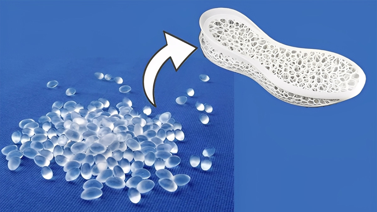
TPU (Thermoplastic Polyurethane) injection molded products are widely used in electronics, automotive, medical, and consumer goods for their elasticity, wear resistance, and stability. Yet their unique properties make them sensitive to temperature, pressure, and moisture, leading to common molding issues like bubbles, sink marks, warpage, or incomplete filling that hurt quality and raise costs. This post breaks down these frequent problems, their root causes, and actionable fixes to help you optimize processes, cut waste, and make high-quality TPU parts consistently.
- Why It Is Important
- 1. Sink Marks
- 2. Bubbles
- 3. Cracks
- 4. Warping and deformation
- 5. Burn marks or black streaks
- 6. Flash
- 7. Product sticking to the mold (difficulty in demolding)
- 8. Decreased toughness
- 9. Insufficient filling(short shot)
- 10. Weld Lines
- 11. Poor Surface Gloss
- 12. Flow Marks (Flow Lines)
- 13. Screw Slippage ( Failure to Feed)
- 14. Screw Won’t Rotate
- 15. Nozzle Leakage (Drooling) in Injection Molding Machine
- 16. Incomplete Material Melting
Why It Is Important
During the injection molding of thermoplastic polyurethane (TPU), the dried and preheated TPU granules are fed from the injection molding machine’s hopper into the heated barrel. When they are in a molten state, they are injected into the relatively low-temperature closed mold through the propelling action of the screw (or plunger) and the nozzle at the front end of the barrel. The mold is filled, cooled and solidified under pressure, and the TPU product is obtained after demolding, which is identical to the mold cavity.
From the TPU injection molding process, it can be seen that the most important molding conditions for TPU injection molded products are temperature, pressure, and time, which affect plasticization flow and cooling. Given the characteristics of TPU, especially its narrow processing temperature fluctuation range, it is required that the injection molding machine must have precise temperature adjustment and control systems, otherwise various factors will cause product defects. If we include the causes of secondary waste products in the four main factors, then they should be raw materials, molds, injection molding machines, and injection conditions.
TPU molded products are generally manufactured according to standard specifications. However, their variations are still quite extensive and unexpected. Sometimes, defects such as dents, bubbles, cracks, and deformations may occur during the production process. Therefore, it is necessary to understand and diagnose the problems from the defective products and propose solutions, which requires professional skills and practical experience. In fact, sometimes just changing the operating conditions or making slight adjustments to the raw materials, molds, and machines can solve the problem. This article takes the production of TPU products using a screw injection molding machine as an example, lists the possible problems and causes of defects in TPU injection molded products, and discusses solutions.
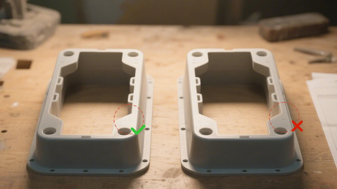
1. Sink Marks
The sink marks on the surface could compromise the quality and strength of the finished product, as well as its appearance. The causes of these sink marks are related to the raw materials used, molding techniques, and mold design, including factors such as the shrinkage rate of the raw materials, injection pressure, mold design, and cooling mechanisms.
Table 1 shows the possible causes and treatment methods of sink marks
| Cause | Solution |
|---|---|
| Insufficient mold feeding | Increase feeding quantity |
| High melt temperature | Reduce the melt temperature |
| Short injection time | Increase injection time |
| Low injection pressure | Increase injection pressure |
| Insufficient clamping pressure | Increase the clamping pressure appropriately |
| Improper mold temperature | Adjust to appropriate temperature |
| Asymmetrical gate | Adjust mold inlet size or position |
| Poor exhaust at the concave part | Set exhaust holes at the concave part |
| Insufficient mold cooling time | Extend the cooling time |
| Wear of screw anti-reversing ring | Replace the screw anti-reversing ring |
| Uneven product thickness | Increase the injection pressure |
2. Bubbles
In the injection molding process, products sometimes exhibit many bubbles, which can affect their strength and mechanical properties, and greatly affect their appearance. Usually, due to uneven thickness of the product or protruding ribs on the mold, the cooling speed of the material in the mold is different, leading to uneven shrinkage and easy formation of bubbles. Therefore, special attention must be paid to mold design.
In addition, if the raw materials are not fully dried and still contain some moisture, they will decompose into gases when heated during melting, which can easily enter the mold cavity and form bubbles. Therefore, when bubbles appear in the product, the following factors can be checked and addressed.
Table 2 presents potential causes and corresponding solutions for the formation of bubbles
| Cause | Solution |
|---|---|
| Raw materials are damp | Thoroughly bake them to dryness |
| Insufficient material injection | Check temperature, injection pressure and injection time |
| Excessive injection speed | Reduce the injection speed |
| Excessive raw material temperature | Reduce the temperature of the melted material |
| Low back pressure | Increase back pressure to appropriate level |
| Fracture surface, overly thick ribs or column | Change the finished product design or the overflow position |
| Overly small sprue overflow port | Increase the sprue and inlet |
| Uneven mold temperature | Adjust the mold temperature to be uniform |
| Excessive screw retreat speed | Reduce the screw retreat speed |
3. Cracks
Cracks are a fatal flaw in TPU products, usually manifested as hair-like cracks on the surface of the product. When the product has sharp edges and corners, fine cracks that are difficult to see often occur at these locations, which is very dangerous for the product. The main reasons for cracks occurring during production are as follows:
- Difficulty in demolding;
- Overfilling;
- The mold temperature is too low;
- Defects in the structure of the product.
To avoid cracks caused by poor demolding, the molding space of the mold must be provided with sufficient demolding slope, and the size, position, and form of the ejector pin must be appropriate. During ejection, the demolding resistance of each part of the finished product should be uniform.
Over-filling is caused by applying excessive injection pressure or metering too much material, resulting in excessive internal stress in the product, which can cause cracks during demolding. In this state, the deformation of mold components also increases, making it more difficult to demold and contributing to the occurrence of cracks (or even breakage). At this time, the injection pressure should be reduced to prevent over-filling.
The gate area is often prone to excessive internal stress, and the area near the gate is prone to embrittlement, especially the direct gate area, which is prone to cracking due to internal stress.
Table 3 shows the possible causes and solutions of cracks
| Cause | Solution |
|---|---|
| Excessive injection pressure | Reduce injection pressure, time, and speed |
| Excessive filler | Reduce raw material metering |
| Insufficient melting cylinder temperature | Increase the temperature of the melting cylinder |
| Insufficient demolding slope | Adjust demolding slope |
| Improper ejection method | Overhaul the mold |
| Metal embedded parts | Adjust or modify the mold |
| Insufficient mold temperature | Increase the mold temperature |
| Too small or improperly shaped gate | Modify |
| Insufficient part demolding angle | Overhaul the mold |
| Demolding chamfering | Overhaul the mold |
| The finished product cannot be properly demolded | Overhaul the mold |
| Vacuum phenomenon in the mold during demolding | Slow down the mold opening or ejection, and add an air inlet device |
4. Warping and deformation
The reasons for warping and deformation of TPU injection molded products are insufficient cooling and setting time, excessive or uneven mold temperature, and asymmetric runner system. Therefore, the following problems should be avoided in mold design:
- Excessivethickness difference in the same plastic part;
- Excessive sharp angles;
- Insufficientbuffer zone, resulting in a significant difference in thickness between turns;
In addition, it is important to set the appropriate number of ejector pins and design a reasonable cooling flow channel for the mold cavity.
Table 4 presents potential causes and solutions for warping and deformation
| Cause | Solution |
|---|---|
| Unfinished cooling when demolding | Extend the cooling time |
| Asymmetric shape and thickness of the product | Change the molding design or add reinforcing ribs |
| Excessive filler | Reduce injection pressure, speed, time and raw material dosage |
| Uneven feeding through the gate | Change the gate or increase the number of gates |
| Unbalanced ejection system | Adjust the position of the ejection device |
| Uneven mold temperature | Adjust the mold temperature to achieve uniformity |
| Excessive raw material buffering | Reduce raw material buffering |

5. Burn marks or black streaks
The phenomenon of black spots or stripes on the product is primarily attributed to the poor thermal stability of the raw materials, resulting from their thermal decomposition.
The effective countermeasures to prevent the occurrence of scorch marks or black streaks are to prevent the temperature of the raw materials in the melt cylinder from being too high and slow down the injection speed. If there are scars or gaps on the inner wall of the melt cylinder or the screw, some raw materials will adhere to them, and this part of the raw materials will undergo thermal decomposition due to overheating. In addition, the check valve can also cause thermal decomposition due to the retention of raw materials. Therefore, special attention should be paid to preventing the occurrence of scorch marks or black streaks when using raw materials with high viscosity or easy decomposition.
Table 5 shows the possible causes and solutions for burn marks or black streaks
| Cause | Solution |
|---|---|
| Excessive raw material temperature | Reduce the temperature of the melted material |
| Excessive injection pressure | Reduce injection pressure |
| Excessive screw speed | Reduce the screw speed |
| Eccentricity between Screw and barrel | Recalibrate |
| Friction heat | Machine maintenance |
| Insufficient nozzle hole diameter or excessive temperature | Readjust the hole diameter or temperature |
| Contaminated raw material in the heating tube(partly blackened through high-temperature quenching) | Overhaul or replace the material tube |
| Mixed raw materials | Re-filter or replace the raw materials |
| Improper exhaust of the mold | Increase the exhaust holes appropriately |
6. Flash
Flash is a common issue in TPU molded products. It occurs when the pressure inside the mold cavity is too high, generating a parting force that exceeds the clamping force of the injection molding machine. This forces the mold to partially open, allowing material to escape and form flash. The causes of flash can be diverse, including issues with the raw material, problems with the injection molding machine, improper machine settings, or even the mold itself. Therefore, when determining the cause of flash, a systematic approach from simple to complex should be adopted.
- Check whether the material is thoroughly dried, whether foreign matter has been mixed in, whether different types of materials have been blended, and whether the material viscosity is suitable.
- Ensure correct adjustment of the injection molding machine’s pressure control system, and match the injection speed settings with the available clamping force.
- Inspect the mold for wear in certain areas, check if venting holes are blocked, and verify whether the runner design is reasonable.
- Examine the injection molding machine for deviations in parallelism between the platens, uneven distribution of force on the tie bars, and wear on the screw check ring and barrel.
Table 6 shows the possible causes and solutions for flash
| Cause | Solution |
|---|---|
| Dampraw materials | Thoroughly bake them dry |
| Contaminated raw materials | Check the raw materials and any impurities to identify the source of contamination |
| Improper raw material viscosity | Check the viscosity of the raw material and the operating conditions of the injection molding machine |
| Insufficient clamping force | Check the pressure value and adjust it |
| Excessive injection and holding pressure | Check the set values and adjust them |
| Late injection pressure conversion | Check the position of the conversion pressure and adjust it to convert earlier |
| Improper injection speed | Check and adjust the flow control valve |
| Improper temperature | Check the electric heating system and the screw speed |
| Insufficient template rigidity | Check the clamping force and adjust it |
| Worn melt cylinder, screw or check ring | Repair or replace it |
| Worn back pressure valve | Repair or replace it |
| Uneven clamping force | Check the tension of the tension rod |
| Unparallel template | Adjust it |
| Blocked exhaust hole of the mold | Clean it |
| Mold wear | Check the number of mold uses and clamping force, repair or replace |
| Improperly fit mold when separating | Check whether the relative position of the mold is offset and adjust it again |
| Unbalanced mold runner | Check the design and make modifications |
| Low mold temperature and uneven heating | Check the electric heating system and repair it |
7. Product sticking to the mold (difficulty in demolding)
When TPU injection molding experiences product sticking, the first consideration is whether the injection pressure or holding pressure is too high. Too much injection pressure can cause excessive saturation of the product, causing the raw material to fill other voids and causing the product to get stuck in the mold cavity, making demolding difficult. Secondly, when the temperature of the melt cylinder is too high, it can cause the raw material to decompose and deteriorate due to heat, resulting in cracks or fractures during demolding, causing sticking. As for mold issues, such as uneven feed ports, which cause inconsistent cooling rates of the product, can also cause sticking during demolding.
Table 7 presents potential causes and solutions for mold adhesion
| Cause | Solution |
|---|---|
| Excessive injection pressure or melt cylinder temperature | Reduce injection pressure or melt cylinder temperature |
| Excessive holding time | Reduce the holding time |
| Inadequate cooling | Increase cooling cycle time |
| Improper mold temperature | Adjust the mold temperature and the relative temperature on both sides |
| Demolding chamfer existing in the mold | Repair the mold to remove the chamfer |
| Unbalanced mold feed port | Limit the raw material flow process and strive to align with the sprue |
| Poor exhaust design of the mold | Set reasonable exhaust holes |
| Mold core misalignment. | Adjust mold core |
| Overly smooth of mold surface | Improve the mold surface |
| Lack of release agent | Use release agent when it does not affect the secondary processing |
8. Decreased toughness
Toughness is the energy required to fracture a material. The main factors that cause a decrease in toughness are raw materials, recycled materials, temperature, and molds. The decrease in toughness of the product will directly affect the strength and mechanical properties of the product.
Table 8 presents potential causes and solutions for reduced toughness
| Cause | Solution |
|---|---|
| Damp raw materials | Thoroughly bake them dry |
| Excessive proportion of recycled materials | Reduce the proportion of recycled materials |
| Improper temperature of the melt | Adjust the temperature of the melt |
| Insufficient mold gate size | Increase the gate size |
| Overly long mold gate junction area | Reduce the length of the gate junction area |
| Insufficient mold temperature | Increase the mold temperature |
9. Insufficient filling(short shot)
Insufficient filling of TPU products refers to the phenomenon where the melted material does not fully flow into all corners of the forming chamber.
The reasons for insufficient filling include:
- improper setting of molding conditions
- imperfect design and manufacturing of molds
- thin walls and thick flesh of molded products
The countermeasures for molding conditions are as follows:
- increase the material and mold temperature
- increase the injection pressure, injection speed, and improve the fluidity of the material.
For molds, the size of the sprue or runner can be increased, or the position, size, and number of sprues can be adjusted and modified to make the molten material flow smoothly. Furthermore, in order to facilitate the evacuation of gas in the forming space, exhaust holes can be set at appropriate locations.
Table 9 shows the possible causes and solutions for insufficient filling
| Cause | Solution |
|---|---|
| Insufficient supply | Increase supply |
| Premature curing of the product | Increase the mold temperature |
| Insufficient melt cylinder temperature | Increase the temperature of the melt cylinder |
| Low injection pressure | Increase injection pressure |
| Slow injection speed | Increase injection speed |
| Short injection time | Increase injection time |
| low or uneven mold temperature | Adjust the mold temperature |
| Blocked nozzle or funnel | Remove and clean it |
| Improper gate position | Adjust and change |
| Small runner | Enlarge the runner |
| Small sprue or gate | Enlarge sprue or gate |
| Worn screw check ring | Replace |
| Trapped gas in mold cavity | Add exhaust holes at appropriate locations |
10. Weld Lines
Weld lines, also referred to as fusion lines, are faint lines formed on a molded part where two or more flow fronts of molten material meet and converge. These lines not only detract from the part’s appearance but also adversely affect its mechanical strength. The primary causes of weld lines include:
- The flow pattern of the material, determined by the part geometry (and corresponding mold construction).
- Poor fusion capability of the molten material at the flow front.
- Entrapment of air, volatiles, or foreign/incompatible materials at the junction where the flow fronts meet.
The severity of weld lines can be minimized by raising the temperature of the material and the mold. Other effective countermeasures involve:
- Relocating or adjusting the number of gates to shift the weld line to a less critical area.
- Incorporating exhaust holesat the fusion junction to facilitate the rapid escape of air and volatiles.
- Adding an overflow well, or “weld line trap”,near the fusion area to divert the weld line into the well, which is later trimmed off from the final part.
Table 10 shows the possible causes and solutions for the weld lines
| Cause | Solution |
|---|---|
| Insufficient injection pressure and time | Increase injection pressure and time |
| Insufficient injection speed | Increase injection speed |
| Low melt temperature | Increase the temperature of the melt cylinder |
| Low back pressure and slow screw speed | Increase back pressure and screw speed |
| Improper gate position, too small gate and sprue | Change the gate position or adjust the mold inlet size |
| Insufficient mold temperature | Increase the mold temperature |
| Excessive rate of solidification | Reduce the curing speed of the material |
| Poor material fluidity | Increase the temperature of the melt cylinder to improve material fluidity |
| Moisture absorption of the material | Increase the exhaust holes and control the material quality |
| Difficulty in discharging air | Add exhaust holes or check whether the exhaust holes are blocked |
| Unclean or mixed material | Check the raw material |
| Excessive dosage of release agent | Use less release agent or try not to use it |
11. Poor Surface Gloss
Poor surface gloss refers to a condition where the surface of a TPU part loses its intrinsic luster, presenting a milky film or a hazy appearance.
This issue is most commonly caused by inadequate polishing of the mold cavity surface. When the cavity surface is in good condition, increasing the material and mold temperature can enhance the part’s surface gloss. The use of excessive mold release agent, particularly oil-based types, is another contributing factor. Additionally, material moisture absorption, the presence of volatiles, or contamination by foreign matter can lead to poor gloss. Therefore, particular attention must be paid to factors related to both the mold and the material.
Table 11 presents potential causes and corresponding solutions for poor surface gloss
| Cause | Solution |
|---|---|
| Insufficient injection pressure and speed | Adjust them appropriately |
| Insufficient mold temperature | Increase the mold temperature |
| Contaminated mold forming space surface by water or grease. | Wipe it clean |
| Inadequate grinding of the mold cavity | Polish the mold |
| Different materials or foreign objects mix in | Clean the material cylinder and filter the raw materials |
| volatile matter in raw material | Increase the temperature of the melt |
| moisture absorption of the raw material | Control the preheating time of the raw material and thoroughly bake the raw material |
| Insufficient dosage of raw material | Increase injection pressure, speed, time and raw material dosage |
12. Flow Marks (Flow Lines)
Flow marks, also known as flow lines, are streaking patterns visible on the part surface, often centered around the gate, which trace the flow path of the molten material.
These marks occur when the initial material entering the cavity cools too rapidly, creating a visible boundary with subsequent material flowing behind it. To prevent flow marks:
- Increase the material temperature to enhance its flowability.
- Adjust the injection speed.
Furthermore, flow marks can be caused by cold material (from the nozzle front) entering the cavity directly. Effective countermeasures include:
- Providing adequate cold slug wells at the intersection of the sprue and runner, or the runner and gate, to trap this initial cold material.
- Enlarging the gate size.
Table 12 presents potential causes and solutions for flow marks
| Cause | Solution |
|---|---|
| Poor melting of raw materials | Increase the melt temperature, back pressure, and screw speed |
| Unclean or mixed raw materials, and insufficient drying | Check the raw material and thoroughly bake it |
| Insufficient mold temperature | Increase the mold temperature |
| Insufficient temperature near the gate | Increase the temperature |
| Insufficient size or wrong position of the gate | Increase the gate size or change its position |
| Short holding time | Extend holding time |
| Improper injection pressure or speed | Adjust to an appropriate level |
| Over thickness variations in product fracture surface | Change the design of the finished product |
13. Screw Slippage ( Failure to Feed)
Table 13 lists the causes and solutions for screw slippage
| Cause | Solution |
|---|---|
| Excessive temperature at the rear section of the material tube | Check the cooling system and reduce the temperature at the rear section of the material tube |
| Damp raw material | Thoroughly bake the raw material and add appropriate lubricant |
| Wear of material tube and screw | Repair or replace |
| Hopper feed issue | Clear the feed section |
| Excessive screw retreat speed | Reduce the speed of the screw's retreat |
| Contaminated material cylinder | Clean the material cylinder |
| Excessive raw material particle size | Reduce the particle size |
14. Screw Won’t Rotate
Table 14 lists the possible causes and solutions for the screw not rotating
| Cause | Solution |
|---|---|
| Low melt temperature | Increase the melt temperature |
| Excessive back pressure | Reduce the back pressure |
| Insufficint lubrication of screw rod | Add proper lubricant |
15. Nozzle Leakage (Drooling) in Injection Molding Machine
Table 15 lists the potential causes and solutions for nozzle leakage
| Cause | Solution |
|---|---|
| Excessive temperature of the material tube | Reduce the temperature of the material tube, especially the nozzle section |
| Improper adjustment of back pressure | Reduce the back pressure and screw speed appropriately |
| Early break off of Cold slug in sprue | Delay the cold slug break-off time |
| Insufficient screw decompression (suck-back) | Increase decompression stroke, modify nozzle tip design |
16. Incomplete Material Melting
Table 16 lists the potential causes and solutions for incomplete material melting
| Cause | Solution |
|---|---|
| Insufficient melt temperature | Increase the melt temperature |
| Low back pressure | Increase the back pressure |
| Insufficient temperature of the lower part of hopper | Close the cooling system at the bottom of the hopper |
| Short molding cycle | Increase molding cycle |
| Insufficient drying of materials | Thoroughly bake the materials |
To gain systematic countermeasures of TPU injection molded products, theoretical support is needed to facilitate the summarization and discovery in practice. As the leading injection molding company in China, KingStar welcomes any corrections or discussions, and please feel free to send us an email(sales@kingstarmold.com) for professional suggestions on TPU injection molded products for your project.
