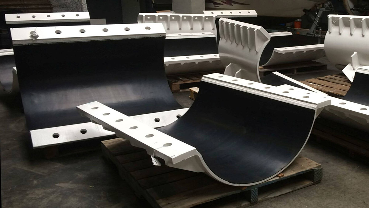
In industries such as chemical and metallurgical, metal equipment and pipelines are easily corroded by chemical media, which not only shortens their service life but may also pose safety hazards. Rubber lining is a practical solution to this problem, which can provide a reliable layer of anti-corrosion protection for metal surfaces. Next, we will explain in detail the complete procedures for rubber lining, including basic requirements, material management, equipment preparation, construction steps, quality inspection, and safe operation.
As the experienced plastic injection molding company in China, KingStar compiled this post which will systematically outline the core points for you.
1.1 Scope of Application & Rubber Sheet Grade Comparison
This Regulation applies to the rubber lining engineering of metal equipment, pipelines, and fittings. For the comparison of new and old grades of commonly used natural rubber sheets, refer to Table 1.
Table 1 Comparison of New and Old Grades of Commonly Used Natural Rubber Sheets
| Types of rubber plates | New brand | Old brand |
| Hard rubber | S1001 | 509 |
| Semi-rigid rubber | S3001 | 1814 |
| Semi-rigid rubber | S3002 | 1751 |
| Soft rubber | 41410 | 1976 |
| Hard rubber | S1002 | 2572 |
| Soft rubber | Sy103 | 4508 |

1.2 Corrosion Resistance & Heat Stability Requirements
The metal surfaces of equipment, pipelines, and fittings are covered with soft and hard rubber to withstand corrosion from chemical media. The corrosion resistance of natural rubber is shown in Table 2.
Table 2 Corrosion Resistance of Natural Rubber
| Media Name | Media Allowable Temperature (°C) | Medium allowable concentration (weight ratio%) | Media Name | Media Allowable Temperature (°C) | Medium allowable concentration (weight ratio%) | ||
| Soft rubber | Hard rubber | Soft rubber | Hard rubber | ||||
| Nitric Acid | 25 | Below 2% | Below 8% | Citric Acid | 65 | Any Concentration | Any Concentration |
| Sulfuric Acid | 65 | Below 50% | Below 60% | Potassium Hydroxide | 65 | / | / |
| Hydrochloric Acid | 65 | Any Concentration | Any Concentration | Potassium Hydroxide | 65 | / | / |
| Phosphoric Acid | 50 | Below 85% | Any Concentration | Lime Milk (Calcium Hydroxide Slurry) | 65 | / | / |
| Hydrofluoric Acid | 65 | Below 0% | Below 50% | Ammonia Water | 50 | / | / |
| Hydrobromic Acid | 38 | Below 50% | Below 50% | Sodium Bisulfate | 65 | / | / |
| Sulfurous Acid | 65 | Any Concentration | / | Ferric Chloride | 65 | Below 50% | / |
| Acetic Acid | 65 | Below 80% | / | Zinc Oxide | 35 | Below 50% | / |
| Oxalic Acid | 65 | Any Concentration | / | Methanol | 65 | Any Concentration | / |
| Lactic Acid | 65 | / | / | Ethanol | 60 | / | / |
| Formic Acid | 38 | / | / | Propyl Alcohol | 55 | / | / |
1.3 Physical and Mechanical Properties of Vulcanized Rubber
The physical and mechanical properties of commonly used vulcanized rubber (including specific gravity, tensile strength, flexural strength, etc.) are specified in Table 3.
Table 3 Physical and Mechanical Properties of Commonly Used Natural Rubber
| Type | Grade | Specific Gravity | Tensile Strength (MPa) | Flexural Strength (MPa) | Elongation at Break (%) | Permanent Set (%) | Heat Resistance (Martens) (°C) | Impact Strength (kg·cm/cm³) |
| Soft | 41410 | 1.12 | 4.5 | — | 275 | 20 | — | — |
| Semi-rigid | S3001 | 1.33 | 30 | 62.5 | — | — | 50 | 2.3 |
| Semi-rigid | S3002 | 1.32 | 22 | 55 | — | — | 40 | 3.0 |
| Rigid | S1001 | 1.26 | 32 | 34 | — | — | 59 | — |
1.4 Heat Stability Requirements
The rubber lining maintains good heat stability within the following temperature ranges:
- Soft rubber: 65-70 ℃;
- Hard rubber: 30-60 ℃;
When heated for 1-2 hours at a temperature below 80 ℃, both soft and hard rubber can meet the heat resistance requirements.
2. Quality Requirements and Storage of Rubber and Auxiliary Materials
2.1 Quality Requirements for Rubber Materials
1)The surface of the rubber sheet is intact and smooth, without defects such as ripples, bubbles, cracks, and wrinkles;
2)The two sides and tail of the rubber plate should be neat, without burrs or serrations, and the thickness should be uniform and consistent. Rubber board specifications: width 800-1000 millimeters, length over 10 meters, thickness divided into three types: 1.5 ± 0.25 millimeters, 2 ± 0.25 millimeters, and 3 ± 0.5 millimeters;
3)The rubber sheet should be free of impurities and natural vulcanization phenomenon;
4)The rubber paddle material should be completely soluble in solvent gasoline;
5)The detachment strength between the hard rubber paddle and the metal is over 4MPa.
2.2 Storage of Rubber Plates
1)The rubber sheet should be wrapped with padding on a wooden shaft and hung on a bracket to avoid compression and mutual bonding;
2)The rubber sheet should be stored in a well ventilated semi dark warehouse, avoiding direct sunlight or high temperatures (more than 2 meters away from heat sources) that can cause aging;
3)The temperature inside the storage room is generally 5-25 ℃, and the relative humidity is 40-50%;
4)When storing rubber plates, avoid contact with liquid fuels, oils, acids, alkalis, or other flammable substances;
5)Self processed rubber plates shall not exceed 50 kilograms per roll. Fine cloth or plastic shall be used as padding on the rubber plates and rolled onto wooden shafts. Talc powder shall not be used as a substitute for padding.

2.3 Rubber Paddle
2.3.1 Preparation Method and Requirements
1)When preparing, first remove any debris on the surface of the rubber paddle board (such as talcum powder, cotton wool, etc.), cut it into pieces with scissors, and place it in a mixing bucket. Inject solvent gasoline and stir at room temperature;
2)Using manual or mechanical mixing, the mixing should be uniform, but the time should not be too long to prevent self vulcanization;
3)The rubber material should be completely dissolved in the solvent and should not clump or precipitate;
4)The prepared mortar should be allowed to stand still naturally for at least 24 hours, and the upper slurry should be used;
5)Rubber paddle ratio: Sy103 (4508) rubber material: gasoline=1:6~1:10; S1002 (2572) rubber material: gasoline=1:8~1:10.
2.3.2 Storage of Rubber Paddles
The prepared rubber paddles should be stored in a sealed container for about one month to prevent aging and failure.
2.4 Technical requirements for auxiliary materials – gasoline
1)The initial boiling point shall not be lower than 80 ℃;
2)At a temperature of 110 ℃, the distillate should not be less than 93%;
3)Dry point not exceeding 120 ℃;
4)Residue not exceeding 1.5%;
5)No moisture, no oil stains, and no water-soluble acid or alkali.
3. Technical Requirements for Metal Equipment Body
3.1 Requirements for Metal Materials and Metal Equipment Structures
1)The carbon steel and cast steel equipment with lining should have a certain degree of rigidity and strength, and withstand a pressure of 1.5 times the vulcanization pressure;
2)When designing, consideration should be given to whether each part of the equipment can be operated with hands or tools inserted;
3)All edges and corners of the lining metal parts must be processed into a circular arc shape with a radius of not less than 5 millimeters, and some special parts are allowed to be no less than 3 millimeters;
4)The surface of metal equipment must be flat, without obvious scars, pockmarks, wrinkles, cracks, slag inclusions, and bumps larger than 3 millimeters, as well as defects such as bubbles, pores, sand holes, etc;
5)Welding equipment should use double-sided butt welding, with no porosity or weld bead in the weld seam. The slag should be removed completely, and the height of the weld seam should not exceed 2-3 millimeters;
6)Riveted parts must use countersunk rivets;
7)Before lining the equipment, the pipe joints and other parts should be pre-constructed, and hot work, cutting, and welding are strictly prohibited after lining;
8)Pressure equipment containers must undergo a pressure test and pass it before leaving the factory;
9)When lining large equipment with adhesive, it should be manufactured in several sections and connected with bolts; If segmentation is not possible, there should be a manhole with a diameter greater than 500 millimeters or an elliptical manhole with a diameter of 500 × 400 millimeters;
10)Static balance tests should be conducted before lining fast rotating components such as centrifuge drums, blower impellers, etc; The pipes and fittings are connected by flanges instead of threaded connections. The maximum length allowed for lined pipes and fittings complies with Table 4.
Table 4 Maximum Allowable Length of Pipes and Fittings
| Pipe Diameter (mm) | Pipe Length (mm) | Tee (mm) L | Cross (mm) h |
| 25 | ≤1000 | 100 | 60 |
| 38 | ≤1000 | 150 | 75 |
| 50 | ≤2000 | 200 | 100 |
| 75~100 | ≤3000 | 250~300 | 125~150 |
| 125~200 | ≤3000 | 350~500 | 175~300 |
Note: When the inner diameter of the straight pipe exceeds 200 millimeters, the maximum length can be determined according to specific circumstances; When the inner diameter of tees exceeds 200 millimeters, their length should not exceed twice the diameter.
Bent pipes and similar fittings should have a bending angle of not less than 90 ° and a bending radius of not less than 4 times the pipe diameter; Two bends are not allowed on a plane, and curved sections are only allowed within one plane.

3.2 Technical requirements for acceptance before equipment processing
1)Before processing the equipment, it should be checked whether it meets the design drawings and technical requirements;
2)Pressure vessels must have a pressure inspection certificate before lining can be carried out, otherwise a pressure test must be conducted first to ensure compliance.
4. Metal surface treatment
4.1 Quality Requirements for Metal Surfaces After Sandblasting
1)The surface should show a uniform and consistent metallic color;
2)Remove metal oxides or other attachments;
3)Oil stains and spots are not allowed to exist;
4)After treatment, the surface should be dry and not contaminated by other substances.
4.2 Transportation and Storage of Treated Surfaces
The processed metal surface should be coated with the first coat of adhesive within 3-6 hours; If the surface is exposed to rain, snow, or air for too long and does not meet the requirements, it should be sandblasted again.
5. Construction Process of Rubber Lining
5.1 Surface Treatment
1)After sandblasting, remove surface dust and sand particles and rust at the bottom of the equipment, or blow them away with compressed air, and then wipe the surface with cotton cloth soaked in gasoline to remove oil and grease;
2)Equipment for sandblasting in winter should wait until the temperature reaches room temperature before applying adhesive to prevent the metal surface from absorbing moisture and affecting bonding;
3)After sandblasting treatment, the equipment should be coated with the first layer of adhesive within 3-6 hours to prevent atmospheric corrosion.
5.2 Rubber Cutting
1)Before use, check whether the appearance quality, brand, and specifications of the rubber sheet meet the design requirements. Only after passing the inspection can it be used;
2)Accurately cut the material during cutting, save rubber sheets and minimize connections. For special and complex components, make samples first;
3)Determine the edge cutting location and overlapping direction based on the equipment structure. The overlapping width is generally 30-50 millimeters, for small pipes it is 15-20 millimeters, and the minimum should not be less than 10 millimeters; Cut the edge of the cut rubber sheet into a groove about 10 millimeters wide with a steel knife.

5.3 Coating With Adhesive Slurry
1)Before applying glue, wipe off the water on the glue board or use water to trim the edges. Wait for the water to completely evaporate before treating the surface;
2)Use a wire brush to remove impurities such as dirt and talcum powder from the rubber plate;
Mix the adhesive evenly before painting;
3)Apply three coats of adhesive on the surface of metal equipment and two coats of adhesive on the surface of rubber plates. If the adhesive is too thin, an additional coat can be applied;
4)Refer to Table 5 for the drying time of the adhesive slurry (greenhouse temperature of 20-25 ℃, relative humidity of 70%);
Table 5 Drying Time of Adhesive Slurry
| Number of Drying Times | Drying Time | Degree of Dryness |
| 1 | 15~20 minutes | non stick to hands |
| 2 | 20~30 minutes | non stick to hands |
| 3 | 2~3 hours | non stick or slightly stick to hands |
The coating should be uniform and consistent, without flow marks, and should not be too thick or form bubbles. When applying the first coat of adhesive, if there are bubbles on the adhesive board, puncture it with a needle and seal the pinhole with adhesive.
5.4 Filling Strips
1)Metal equipment corners, welds, and other uneven areas should be leveled with adhesive strips coated with glue, and then baked flat with a soldering iron below 80 ℃;
2)When the equipment defect is deep, lead can be used to fill it up;
3)The adhesive used for filling the rubber strip must be the same as the adhesive used for lining.
5.5 Bonding
1)The hanging line exhaust method can be used according to the shape of the workpiece and the distribution of defects. The hanging line should be carried out before the adhesive is close to drying and the adhesive board is bonded, and the wire end should be led out of the equipment;
2)When laying the adhesive board, roll up the coated adhesive board with clean insulation wax cloth and send it to the equipment or pipeline. The position should be correct, without wrinkles or thinning under tension. The adhesive film should be kept intact during lining;
3)Ensure that the air on the bonding surface is completely expelled and tightly pressed during bonding;
4)The bonding sequence must comply with the rules: vertical equipment should be bonded from bottom to top, and horizontal equipment should be bonded from top to bottom; Material export connection should be affixed first, and import connection should be affixed later; The joint of the adhesive board should be oriented in the direction of the medium flow or the direction of rotation of the rotating equipment;
5)When lining with double-layer adhesive sheets, the lap joints of each layer should be staggered with a minimum spacing of 100mm and should not overlap;
6)The lining rubber parts that need to be processed after vulcanization should have a processing allowance for the lining thickness;
7)During the bonding operation, the lining film should not come into contact with objects to prevent deformation, and excessive stretching is not allowed to affect the uniformity of thickness.

5.6 Gluing
1)The temperature for gluing is generally 100-180 ℃, and the hot soldering iron should not stay on the glue board;
2)Start from one end to the other, and if the area is too large, start from the middle. Do not burn randomly;
3)Try to maintain one direction and burn them one by one;
4)If bubbles appear, use a needle to puncture and release the air, then use a soldering iron to compact it;
5)After bonding each layer of rubber, an intermediate inspection is required: visually inspect the appearance quality, check whether the dimensions comply with the drawings, check the direction of joint overlap and the tightness of the fit, and check for any missing or burnt marks; After each layer of adhesive is lined, use a spark detector to check for qualification before proceeding to the next process.
5.7 Sulfurization
5.7.1 Sulfurization Method
According to the external dimensions and structural characteristics of the equipment, it is divided into three types: indirect vulcanization, direct vulcanization, and open vulcanization. Indirect vulcanization is suitable for small-sized equipment, pipelines, and fittings, and can be placed in a vulcanization tank to pass steam; Direct vulcanization is suitable for equipment with a large appearance and the ability to withstand a steam pressure of 0.3MPa. It can be directly steam cured (bulk vulcanization); Open end vulcanization is suitable for equipment with a large appearance, which cannot enter the vulcanization tank and cannot withstand pressure and sealing. It uses open boiling water vulcanization.
5.7.2 Indirect Vulcanization Operation Regulations
1)Before vulcanization, check whether the vulcanization tank, steam pipeline, pressure gauge, safety valve and other accessories are safe, and do not use inappropriate bolts and nuts;
2)During vulcanization, first open the drain valve and vent valve to release cold air and cooling water, so that the temperature inside the tank is consistent, and then gradually increase and decrease the pressure;
3)Strictly control the process conditions, ensure sufficient steam source, avoid pressure fluctuations, and avoid generating negative pressure;
4)Operate according to the process regulations, without significant fluctuations to avoid affecting quality;
5)During the vulcanization period, operators are not allowed to leave their posts. If they need to leave their posts, they must find someone to replace them;
6)After vulcanization, reduce the steam pressure to zero, open the vent valve and drain valve, cool down, and then open the vulcanization tank cover to check the quality;
7)Operators should keep job records.
5.7.3 Sulfurization Time of Commonly Used Adhesives
Table 6 Sulfurization Conditions
| Adhesive Code | S3002 | S1001 | S3001与41410 | |||
| Thickness | 3~4.5mm | 3~4.5mm | 4.5mm | |||
| Steam Pressure & Time
Operation Step |
Steam Pressure (Gauge MPa)) | Time (min) | team Pressure (Gauge MPa) | Time (min) | Steam Pressure (Gauge MPa) | Time (min) |
| Pressure Increase | 0-0.15 | 30 | 0-0.15 | 20 | 0-0.10 | 20 |
| Pressure Hold | 0.15 | 30 | 0.15 | 5 | 0.10 | 10 |
| Pressure Increase | 0.15-0.24 | 20 | 0.15-0.30 | 30 | 0.10-0.20 | 20 |
| Pressure Hold | 0.24 | 20 | 0.30 | 180 | 0.20 | 10 |
| Pressure Increase | 0.24-0.30 | 20 | / | / | 0.20-0.28 | 20 |
| Pressure Hold | 0.30 | 270 | / | / | 0.28 | 180 |
| Pressure Decrease | 0.30-0.24 | 30 | 0.30-0.15 | 30 | 0.28-0.15 | 20 |
| Pressure Hold | 0.24 | 40 | 0.15-0 | 20 | 0.15 | 10 |
| Pressure Decrease | 0.24-0.15 | 30 | / | / | 0.15-0 | 30 |
| Pressure Hold | 0.15 | 20 | / | / | / | / |
| Pressure Decrease | 0.15-0 | 30 | / | / | / | / |
| Total Time | / | 540 | / | 285 | / | 320 |
5.8 Defect Repair
If defects such as delamination, cracks, needle holes, and scorching are found after vulcanization, the defects should be carefully removed first, and grooves should be excavated around the adhesive layer (for multi-layer lining equipment, grooves should be excavated at certain intervals for each layer of rubber sheet), and then surface treatment can be carried out. Three methods can be selected: secondary vulcanization or local vulcanization of the original rubber material, corresponding process repair of other types of rubber sheets, and repair with fiberglass/adhesive/rubber repair agents.

6. Quality Standards and Inspection Methods
6.1 Quality Standards
1)The area of detachment (bubble) between the rubber plate and the metal shall not exceed 20 cm ², and the height shall not exceed 2 mm; The allowed quantity is divided according to the lining area: no more than 3 areas with a lining area greater than 4 square meters, no more than 2 areas with a lining area of 2-4 square meters, and no more than 1 area with a lining area less than 2 square meters;
2)When lining pipes, fittings, and similar parts, the protrusion height shall not exceed 2 millimeters, the length shall not exceed 50 millimeters, and the width shall not exceed 20 millimeters; The total area of protrusions should not exceed 2% of the total area of the lining parts; A flange plane is allowed to have a protrusion area of no more than 4 cm ² and no more than 2 protrusions separated from the layer;
3)Rubber lined components that require automotive processing must not have protrusions or detachment of the rubber lining layer from the metal surface;
4)The bonding strength between hard and semi-rigid rubber and equipment should reach 4-6 MPa;
5)When using a spark detector to check the lining surface, there should be no electrical leakage;
6)The lining surface shall not be scalded to a frosted finish;
7)The overlapping direction of the rubber plate should be reasonable and meet the process requirements.

6.2 Inspection Methods
- Appearance quality inspection: By directly observing the surface of the lining with the naked eye, check for defects such as protrusions and loose joints.
- Knocking inspection: Use a wooden hammer to strike the surface of the lining, and the qualified parts should emit a crisp and pleasant metallic sound; If the voice is hoarse, it indicates that there is a defect in the detachment layer in that area.
- Spark detection: A spark detector is used for inspection, with a detection voltage standard of 3000V per millimeter of adhesive layer thickness. There should be no leakage during the detection process.
- Key project acceptance: After the completion of larger key projects, company leaders, technicians, and workers need to jointly participate in the acceptance to ensure that the project quality meets the requirements.

7. Security Technologies
- Flammable substance protection: In workplaces where flammable substances such as gasoline and adhesive are present, smoking and fire must be strictly prohibited to eliminate potential fire hazards.
- Spark prevention: When handling volatile solvents in the workplace, it is necessary to avoid sparks caused by friction or impact between electrical equipment and metal surfaces to prevent fires or explosions.
- Equipment internal operation protection: When operating or inspecting equipment or pipelines, operators must wear complete labor protection equipment; It is prohibited to carry matches, lighters, metal objects, and other flammable substances, and hard soled shoes with nails must not be worn to avoid scratching the lining or generating sparks.
- Lighting safety: The voltage of the mobile safety lighting used during operation must be controlled below 36 volts to prevent electric shock accidents.
- Material storage: The storage amount of solvents and adhesives in the operating area shall not exceed the usage amount on duty; The storage container should be tightly sealed and kept by a dedicated person.
- Static protection: For equipment or pipelines that are inconvenient to access, static grounding devices must be installed before entering the interior for construction to eliminate the risk of static electricity.
- Safe use of soldering iron: The soldering iron heating furnace should be sealed and placed outdoors or in a room that is not connected to the operating area; The temperature of the soldering iron must be strictly controlled within the specified range, and it is strictly prohibited to use a red hot soldering iron to apply glue to prevent the glue board from burning.
- Homework monitoring and rotation: When applying adhesive and cleaning with gasoline, there should be a dedicated person around the operation area to monitor; When constructing in enclosed equipment and pipelines, it is necessary to strictly follow the rotation operation system to avoid operators being in a sealed environment for a long time.
- Firefighting facilities: The operation site must be equipped with necessary firefighting equipment, such as fire extinguishers, firefighting sand, etc., and ensure that they are in good condition and available for timely disposal in case of sudden fire incidents.
- Ventilation and gas prevention: Good natural or mechanical ventilation should be maintained at the operation site to reduce the concentration of volatile solvents and prevent poisoning of operators.
- Safe operation of vulcanization tank: The lid of the vulcanization tank must be tightened before steam can be introduced; The pressure gauge needs to be inspected within the prescribed period to ensure accurate readings; The safety valve must be sensitive, reliable, and able to release pressure normally; The operator of the vulcanization tank shall not leave their post without authorization and shall monitor the operation status of the equipment throughout the process.
- Safety of opening the lid of the vulcanization tank: It is strictly prohibited to open the lid of the vulcanization tank before the steam is completely discharged. It can only be opened after the pressure inside the tank drops to zero and the temperature drops to a safe range to prevent steam burns or equipment damage.

8. Other Instructions
This regulation is mainly formulated for the construction of natural rubber lining. There are no specific regulations for the lining construction of chloroprene rubber (CR), butyl rubber (IIR) and other special rubber types in synthetic rubber. Such construction generally needs to be carried out in accordance with the relevant process specifications provided by the manufacturers of each rubber type.
The various stages of rubber lining technology are interrelated, from rubber material selection and storage, to metal equipment pretreatment and lining construction, to quality inspection and safe operation, all of which are indispensable. Strictly following this regulation can not only ensure anti-corrosion performance and extend equipment life, but also safeguard the bottom line of production safety. The construction of special rubber types requires reference to the manufacturer’s special regulations, and the mature system of natural rubber lining also provides valuable process templates for the industry, helping enterprises achieve the goal of equipment anti-corrosion, high efficiency, safety, and durability.
If you need to gain a deeper understanding of rubber lining process regulations in solving application problems or want to source custom manufacturing company for your projects, please feel free to contact our technical team at sales@kingstarmold.com or leave an online message. For more industry resources, please continue to follow KingStar, the leading injection molding company in China.