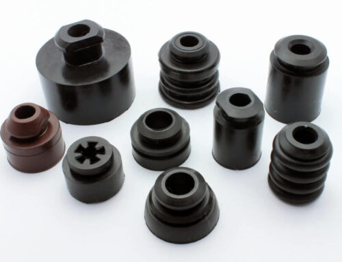
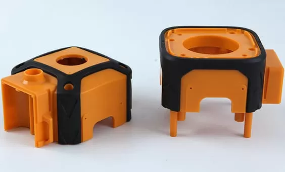
Whether the overmolding mold is qualified is crucial, as the design of the mold structure and the mold fitting(FIT) process during manufacturing are extremely important. All personnel involved in the design and manufacturing processes must remember that the optimal effect of the overmolding product should be identical to that achieved with a two-shot mold. Therefore, the FIT process for our overmolding molds should be treated as equally important as that for two-shot molds. Every manufacturing step can impact the final FIT outcome, and any processing result is closely related to mold progress and product quality. This comprehensive guideline outlines the critical requirements across the entire workflow—from design and CNC machining to mold fitting and trial—to ensure final products achieve a seamless, high-quality bond between rigid and soft materials.
1. Design Requirements
1) Due to the small contact area of the mold parting surface, balance blocks must be added to the mold base.
2) When designing overmolding molds, standard small gate mold bases are typically used, and during secondary injection, the first-shot parts should be placed as far forward as possible on the front mold.
3) The wall thickness for the overmolding soft material should ideally be between 1.3mm and 1.8mm (preferably around 1.5mm). Otherwise, it is recommended to advise the customer to modify the fit when reviewing the product drawings. If the wall thickness is less than 1.3mm, the material flow will be difficult. If the wall thickness exceeds 1.8mm, it will increase the risk of shrinkage during production.
4) The gate design of the overmolding molds is very important, and the gate locations must fully consider the balance of the plastic flow. The size of the gate must be adjustable. The gate diameter in large soft-material areas cannot exceed φ1.5mm, nor φ0.8mm for small areas. In order to ensure balanced flow, it is recommended to make all gates smaller than φ0.8mm first, so that they can be adjusted on the injection molding machine during the first trial molding. The secondary injection molding of the overmolding mold is for soft materials, and the small end of the mold nozzle cannot be larger than φ2.5mm to prevent sticking during production. The large end cannot be larger than φ6mm, otherwise the nozzle will short due to insufficient cooling. In order to prevent runner sticking, The design of the mold and flow runner should adopt a U-shape as much as possible, and the single-sided slope of the flow runner should be connected with a unilateral draft of 15° with a smooth radius (R) transition. The flow runner and the large end of the small water gate should not exceed 6mm, and the gate ejector pins must be processed according to the company’s standards.
5) The ejection system of an overmolding mold must consider the balance of ejection, otherwise the soft material is prone to deformation after ejection and cannot directly balance the ejected product. When designing the structure, it is necessary to consider angle-lift mechanisms to improve the ejection balance problem.
6) In order to ensure that the appearance of the overmolding parts ejected after overmolding injection molding is qualified, the designed ejection device must be inserts made of rigid plastic materials such as ABS or acrylic.
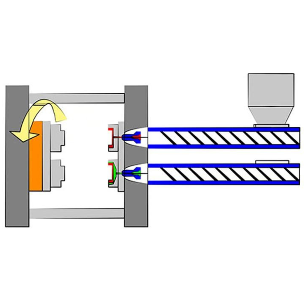
7) If the structure of the overmolding mold has row sealing, the row should be designed as close to the front mold as possible, because the row of the front mold is convenient for FIT.
8) In order to ensure the strength of the sealing ledge, the secondary injection material is a soft plastic product, and the sealing ledge width should not be less than 0.8mm as much as possible. The secondary injection material is a rigid plastic product, and the sealing ledge width should not be less than 1.0mm as much as possible. Otherwise, it is recommended that the customer modify the product to match.
9) For optimal results when fitting the front and rear molds together, the plastic plate removed after fitting should show no compression damage or abrasions. The sealing compound should form an even bead along the mold joint, with no compression marks. The rigid plastic should exhibit no white marks or swelling from pressure on the core pins or ejector pins. After confirming the front and rear molds are properly aligned, proceed to the final assembly.
10) The runners, nozzles, gates, and ejector pins of the soft plastic mold must be machined according to design specifications.
11) Trapped air is highly likely to occur during secondary injection molding. Therefore, when designing overmolding molds, thorough consideration must be given to venting. Filling material in dead corners is particularly challenging. All dead corners and long runner sections must incorporate vent holes on the rigid plastic layer. Additionally, the diameter of all soft plastic gate openings and vent holes must not be less than 2.5mm (φ2.5mm), otherwise breakage is likely during production.
12) Regardless of whether the overmolding material is soft or rigid plastics, to ensure complete fusion between primary and secondary injection molding materials and achieve qualified thrust, the first shot of secondary injection molded products must incorporate a snap-fit feature at the corner positions.
13) At the sealing line locations for soft plastic, the rigid substrate should not be formed across both the front and rear molds. It is preferable to employ a mold insert to define this area. A parting line across the front and rear molds, combined with the presence of draft angles, can easily lead to flash formation during the molding of the soft material.
2. CNC Machining
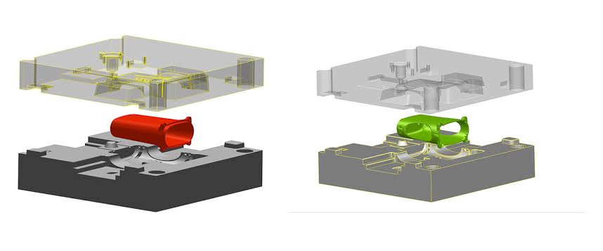
1) Before machining the front mold of a secondary injection soft plastic mold, ensure that the front mold of the overmolding mold matches the rear mold of the primary rigid plastic injection mold. The front mold of the soft plastic mold must not have any clearance.
2) When machining the copper core for the mold’s core position, allow a clearance of 0.1mm-0.15mm on both sides of the core position. No clearance is permitted at the pin position. Regardless of whether it is the core or pin position, no clearance is allowed at the bottom.
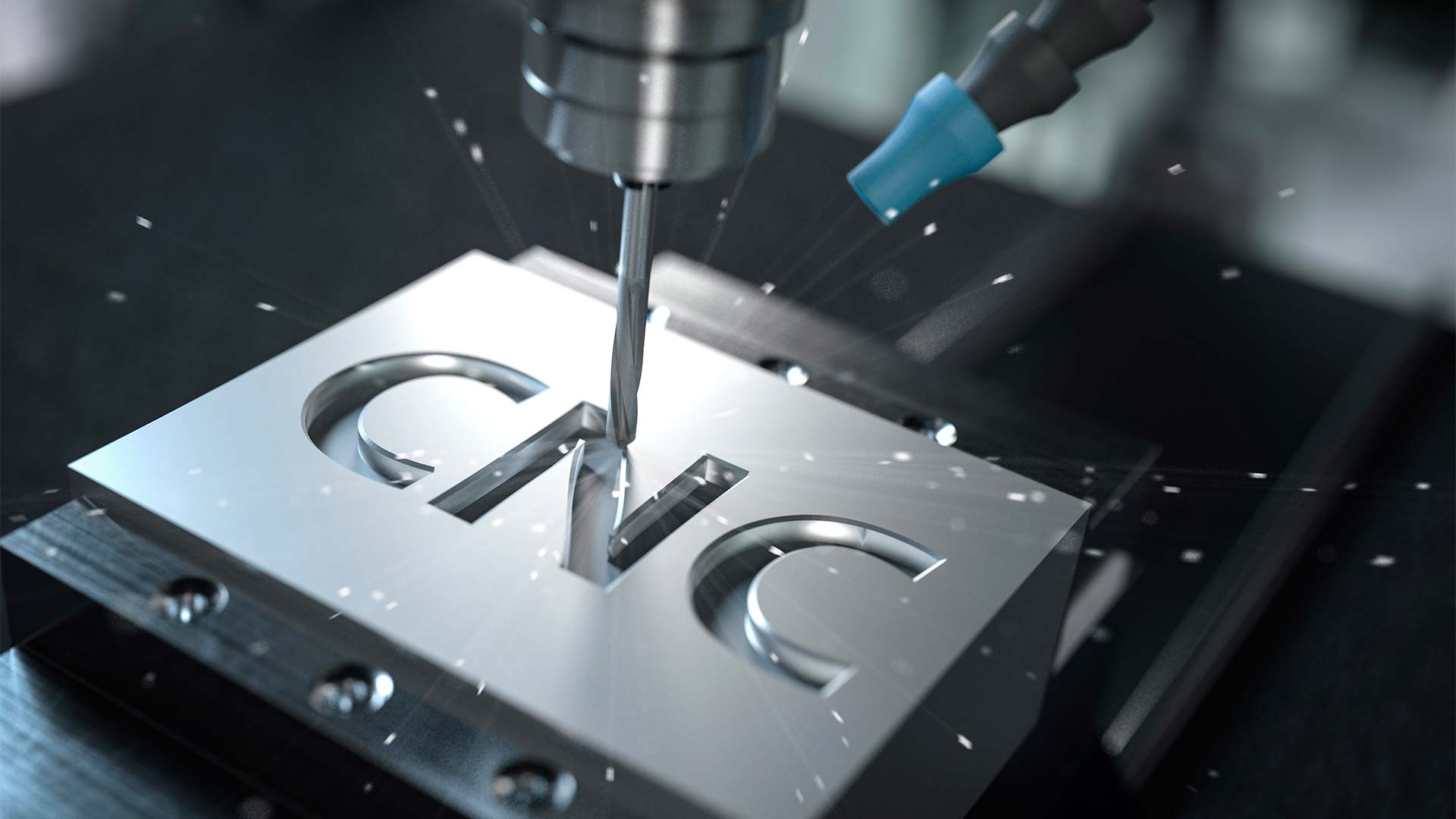
3) After machining the sealing ledge electrodes, it must be ensured that its position aligns precisely with the sealing ledge location on the front mold of the rigid plastic single-shot injection mold. Since the ledge electrodes is typically thin, it is essential to prevent deformation after removal from the machine. If necessary, reinforce the electrode base with aluminum or steel plates. Failure to do so will severely impact the progress of the FIT mold and compromise mold quality.
4) Separate electrodes for rib features from those for blending the main surfaces during manufacturing. This practice prevents issues such as excessive EDM sinking in the rib areas or failure to align the large surfaces properly.
3. EDM Machining
1) When performing EDM machining with electrodes for the overmolding mold, it is essential to verify that the sealing ledge on the rigid plastic mold is uniform. When machining the sealing ledge for the soft plastic mold, particular attention must be paid to ensuring the surrounding sealing edge is consistently around 0.8mm wide. Care must also be taken to prevent deformation of the ledge electrode during its setup and alignment. Regarding dimensions: the ledge electrodes for the rigid plastic mold should be machined to the exact specified depth, while those for the soft plastic mold should be machined approximately 0.02mm shallower than the nominal depth.
2) The machining depth for all rib and boss electrodes must be held to the exact nominal value. If electrode wear is significant, the electrode must be re-machined to ensure the mold fitting process achieves the desired outcome and remains on schedule.
4. Production Team Processing
1) When processing soft and rigid plastic molds for FIT overmolding products, production team members must exercise particular caution to avoid grinding the inner mold steel material or adjusting the core height. Any processing steps involving the inner mold or core height must account for the corresponding position in the other injection mold.
2) When performing secondary injection molding for soft plastic FIT molds, first verify that the mold parting line dimensions and pillow positions meet drawing specifications.
3) Only after confirming that the parting line and cushion position achieve a perfect fit with the mold can the plastic plate fitting process begin. First, take the complete rigid plastic sample to test whether it can be inserted into the soft plastic front mold. Remember: regardless of whether the rigid plastic product contains fibers or has deformed, a properly processed soft plastic front mold should generally fit inside the rigid plastic. If it does not, it may indicate insufficient clearance or incorrect dimensions in the processed soft plastic front mold.
4) Once it is confirmed that the entire plastic plastic sample can be placed into the soft plastic front mold cavity, the plastic plastic component requiring soft plastic overmolding should be cut into small pieces of approximately 15mm-20mm. Each piece should be individually used to perform a fit test against the front mold’s row-by-row surface.
5) If significant gaps or instability are detected between the part and the mold, the clearance between the mold steel and the plastic plastic plate should be less than 0.05mm. Immediately recommend inspecting the CNC machining of the soft plastic front mold steel for abnormalities. If issues are found, rework is mandatory. Remember: avoid extensive welding on the soft plastic front mold.
6) After confirming all cut small parts pass the mold fit test, ensure the rigid plastic sample plate can be placed into the soft plastic front mold cavity without excessive force. Otherwise, it will severely impact cycle efficiency during future trial molding or production. The optimal mold fit should allow the entire plastic plate to be easily removed by hand after placement.
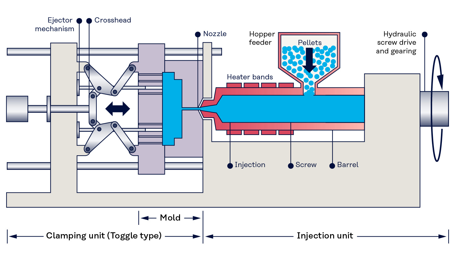
7) After confirming the soft mold front plate has achieved a good fit, proceed to assemble the front and rear plates with the sample for a combined mold fit test. During this initial fit test, avoid excessive force, as it may severely damage the sealing ledge area of the soft mold rear plate. If the sealing ledge differs significantly from the plastic plate, do not directly modify the steel ledge material. Instead, verify whether the EDM (spark erosion) and CNC milling machine front-end machining meet specifications.
8) Rigid plastic sheets made of fibrous materials may exhibit greater deformation. When performing mold fitting, if deformation causes uneven sealing at the plastic ledge, consider adding plastic locally at the sealing ledge position.
9) Achieving the best results with front and rear molds requires a perfect fit. After the mold is assembled, the plastic sheet should be free of compression damage, scratches, and exhibit uniform sealing at the ledge with no compression marks. Rigid plastic should show no white marks or swelling from pin or core pins. After confirming the front and rear molds for soft plastic are optimal, proceed to the final positioning step.
10) The runners, nozzles, gates, and ejector pins for soft plastic molds must be machined according to design specifications.
5. Mold Processing
1) To ensure proper adhesion between plastic and soft plastic , areas where soft plastic will be applied to rigid plastic molds must be free of spark marks. For rigid plastic molds made of fiber materials, these areas must be polished.
2) During the first trial molding of soft plastic molds, do not remove flash from the soft plastic -covered areas; retain the flash to prevent mold adhesion.
3) No flash removal is required for all soft plastic mold runners, nozzles, or small sprues.
4) When removing flash from the sealing ledge of rigid plastic molds, do not use grinding machines. Only manual removal is permitted, gently pushing away the flash.
6. Mold Testing and Monitoring
1) Select the appropriate injection molding machine for soft plastic mold testing.
2) For the first soft plastic mold trial, notify production personnel to adjust the sprue on-site to ensure optimal flow balance.
3) For complex soft plastic molds undergoing initial testing, mold monitoring personnel must collaborate with testing technicians and manufacturing team members to verify proper mold operation after installation.
4) The first soft plastic mold trial must include large flash samples, runner plates, and provided sprues to facilitate mold modifications.
Conclusion:
Achieving a flawless overmolding result demands precision across every stage, from design and machining to the final mold fitting. The guidelines outlined in this document serve as the foundation for manufacturing molds that produce seamless, high-quality products.
At KingStar, a leading injection mold making company in China, we don’t just follow these principles—we master them. With rich experience in one-stop custom manufacturing, we are equipped to bring this level of precision and expertise to your specific project. If you have any more questions on injection mold fabrication or need us to make professional suggestions for your specific project, you’re welcomed to contact us by email (sales@kingstarmold.com) or fill out a form on our contact page.
