As the leading injection molding factory in China, KingStar has extensive experience in overmolding design. This specification is formulated based on the needs of our company’s overmolding design, combined with the practical design, manufacturing, and production conditions within the company. It serves as an internal corporate standard. All referenced standards will be revised, so it is necessary to discuss various aspects and consider the possibility of using the latest standards when applying it.

2. Purpose and Scope
To standardize the design of our company’s overmolding process, reduce design defects caused by overmolding issues, enhance the quality and efficiency of overmolded products, and improve the process reliability, stability, testability, and maintainability of overmolding molds/materials/injection molding production.
The specificion applies to all electric tools with overmolding designs in our company.
3. Terminology

3.3 Overmolding Injection Molding Molds
One material is molded over another material, creating a multi-layer structure. During the two-shot injection molding process, the overmolding material is injected above, below, around, or inside the substrate, combining into a single complete part. This process can be achieved through multiple injections or insert molding. Currently, soft plastic over hard plastic primarily utilizes the two-shot injection molding molds and two-color molds.
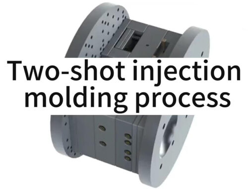
3.3.1 Overmolding Molds (Two-Shot Molding)
The two types of plastic materials do not necessarily undergo injection molding on the same machine but are formed in two separate stages. After the product is demolded and removed from one set of molds, it is then placed into another set of molds for the second injection molding process. This process can also be referred to as insert molding, characterized by:
1) The the substrate (body/skeleton) is usually much larger than the overmolding material;
2) Preheating may be necessary to bring the surface temperature close to the melting point of the overmolding material, thereby achieving optimal bonding strength;
3) Generally, this molding process is typically completed with two sets of molds and does not require a specialized two-color injection molding machine.

3.3.2 Two-color Molds
Two types of plastic materials are molded on the same injection molding machine, formed in two stages, but the product is only demolded once. This molding process is generally referred to as two-color injection molding, typically completed by a single set of molds and requiring specialized two-color injection molding machines.
4. Material Selection and Compatibility
4.1 Requirements for Material Selection and Compatibility
Our overmolded products are all formed using the two-shot injection molding (Insert Mold) method.
The selection of resin materials for two-shot injection molding has multiple factors, which depend on the characteristics of the substrate and the application performance. Specifically, there are the following points:
1) Chemical corrosion resistance.
2) Flame retardancy (in compliance with ecological and environmental requirements) The ecological and environmental protection label is a symbol that indicates that a product meets environmental and social standards.
3) Wear resistance (to prevent indentation or detachment).
4) Shore hardness (meeting softness or other requirements).
5) Impact resistance (meeting structural requirements).
6) Melting point (meeting the application temperature requirements and will not soften or deform).
7) Bonding mechanism (mechanical interlocking is formed when two materials are incompatible, chemical bonding when compatible).
Generally speaking, compatible materials should have similar chemical properties or contain matching composite components. When the substrate and overmold material are incompatible, they usually only form mechanical interlocking rather than chemical bonding.

4.2 Hard Plastic over Hard plastic is Subject to Strict Limitations
Hard plastic can be applied locally, but cannot be used for designs with large areas or forming closed loops, otherwise, as follows:
1)crack
substrate: PA6-GF30;
Adhesive material: ABS
2)Reason
The adhesive area is too large;
The overmolding area has been opened into a closed ring shape;
The curvature (drop point) is too large.
4.2.1 Two-shot Injection Molding with Hard Plastic of the Same Material is Not Allowed
1) Two materials have the same melting point, and during the injection molding process, there may be color mixing, which affects the appearance quality;
2) Hard plastics have a higher injection pressure compared to soft plastics (about 30% or more), and the high pressure often makes it difficult to seal, resulting in flash or damage to the substrate at the pressed area. Hard plastic overmolding has very high requirements for overmolding molds and injection molding processes, and is prone to defects, leading to an increase in production costs. It is not recommended to use it.
For example, if the substrate is PA6-GF30 and the overmold material is also PA6-GF30, the above-mentioned problems such as color mixing, high injection pressure, and leakage/pressure damage of the finished product may occur.
4.2.2 The Overmolding Between Different hard Plastics Must Meet the Following Conditions
1) Two materials should have a difference of molding temperature of at least 30℃ or more; The melting temperature of the substrate should be higher than that of the overmold material;
2) The overmolded (color separation) area of the hard plastics overmolding material should be as small as possible to avoid the risk of cracking caused by the shrinkage of the material’s own volume and shrinkage;
3) The shrinkage rate of hard plastic overmold materials should be small, and non-crystalline or semi crystalline plastics should be used, with a shrinkage rate usually around 0. 4~0. 6%.
When manufacturing overmolding molds, the shrinkage rate cannot be set, and the molding cavity must be manufactured according to the specified area of the substrate (skeleton). After the overmold material is injected into the cavity, it still needs to shrink (material properties thermal expansion and contraction).
Overmolding materials with high shrinkage rate can cause:
- Significant assembly gaps;
- Deformation of the substratesubstrate under stress;
- The self cracking of the overmoldmaterial under tensile stress.
Therefore, the two-shot injection molding between hard plastics, the overmolding area, and the shrinkage rate are two critical issues that must be paid attention to.

4.3 Material Compatibility for Power Tool Overmolding
Considering the instability and low yield of the two-shot injection molding process, it is not recommended to use more than two two-shot injection molding processes for color separation. If you want to put in a lot of effort, it is recommended to use a clip (split) structure to achieve it.
In the case where the substrate material is determined, the priority order for selecting the overmold material (the top is preferred):
| Substrate (Body/Skeleton) | Overmold Material | Remarks |
| PA6—GF | Compatible with all common elastic resins, prefer TPE | TPE wear resistance |
| PA66-GF | Compatible with all common elastic resins, prefer TPE | TPE wear resistance |
| ABS | Compatible with all common elastic resins, prefer TPE | TPE wear resistance |
| PC+ABS/PC | Compatible with all common elastic resins, prefer TPE | TPE wear resistance |
| PP | TPR/TPE/PVC | |
| Metal die-casting parts | TPE/PVC /TPU/PPS/PA6-GF | Design/function/operating conditions need to be considered |
| PA6—GF/PA66—GF/PC | ABS(Not recommended for large areas) | 1. Feasible for small areas like logos (<100mm*20mm).
2. Larger areas require comprehensive consideration of structure and curvature. |
In the case where the overmold material is determined, the priority order for selecting the substrates (the top is preferred):
| Overmold Material | Substrate (Body/Skeleton) | Remarks |
| TPE | Compatible with all engineering plastics / metal die castings | |
| TPU | Compatible with all engineering plastics / metal die castings | |
| PVC | Compatible with all engineering plastics / metal die castings | |
| TPR | Compatible with all engineering plastics / metal die castings | |
| PPS | metal die castings | |
| PA6/PA66—GF | metal die castings | |
| ABS(Not recommended for large areas) | PA6-GF/ PA66-GF/PC | 1. Feasible for small areas like logos (<100mm*20mm).
2. Larger areas require comprehensive consideration of structure and curvature. |
5. Overmolding Structure Design Specification
- Mold Parting Line Grooves on Substrate:All mold parting lines on the substrate must incorporate glue traps (also known as flash grooves or pinch-off grooves).
- Substrate Glue Trap Dimensions: The width of the glue trap on the substrate should be 1.2mm or 1.8mm. A width of 1.2mm is selected for planar seal-off surfaces, while 1.8mm is used for areas with complex seal-off geometries.
- Retention Features in Overmolding Area: Corners or slender sections within the overmolding area require stepped retention holes (pull pins).The periphery of the overmolding area on the substrate should have continuous or intermittent retention grooves, with a depth of 1.0mm and a width of 1.0mm. Retention holes should be plentiful (spaced 20-30mm apart) and positioned as close as possible to edges, corners, and recessed areas. The distance between the edge of a retention hole and any adjacent rib on the substrate skeleton must be≥ This prevents overmold material from bleeding into gaps near ribs, which could cause flash or short shots.

- Angled Seal-off Surfaces on Substrate:When the substrate is sealed with a angle, its angle should not exceed 45 degrees. The sealing surface should be at least 1.2mm wide, parallel or perpendicular to the parting surface as much as possible. If it is a sloping surface, the angle should be as small as possible to reduce the difficulty of mold fitting, and the angle should not exceed 45 degrees.
- Anti-sticking Design for Deep Features: Holes or slotsdeeper than 5mm should have a reverse buckle design at the end of the overmolded section to avoid sticking to the mold
- Structural Detail Requirements:Similar to the two small dots in structure “B”, the process requires that they must be greater than 2 * 2mm. The width of the peripheral reinforcing rib should be at least 1.5mm, and the base should be 2mm (ladder shaped).
- Overmolding Wall Thickness: Recommended value: 1.5mm. The thinnest part in the local area should not be less than 1.0mm. The ratio of TPE flow length (including gate length) to product thickness should be less than 150:1. If the ratio is too large, defects such as short shots and insufficient filling may occur; Product design can be done in a ratio of 80:1.
- Seal-Off Clearance:The sealing gap between structures “R” and “X” must be greater than 1.0mm. Otherwise, there may be sealing problems and flash.

This specification systematically outlines the core requirements for the design of electric tool kit adhesives, covering key aspects such as material selection and structural specifications, providing a unified basis for related design, production, and inspection work. Each department should strictly follow the regulatory requirements and flexibly apply them based on specific product characteristics during the execution process. For problems and improvement suggestions that arise during the implementation of standards, they can be reported to the technical department for subsequent revision and improvement. This specification will continue to be optimized with the company’s technological development and industry progress, helping to enhance product quality and market competitiveness.
If you want to partner a reliable custom manufacturer or need professional suggestions for your specific project, you’re welcomed to contact us by email (sales@kingstarmold.com) or fill out a form on our contact page.