Molds play an essential role in injection molding and die-casting process, and should be designed for continuous, frequent use. A durable mold could bring manufacturing efficiency and production effectiveness.
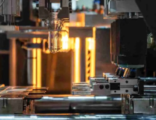
Whether in injection or die-casting, a mold is a specified instrument that enables the transformation of molten plastic or metal into a solid, precisely shaped product. Here is how the process works: First we inject liquefied material into the mold at a certain controlled speed, applying and maintaining a certain pressure while the material cools and solidifies at a certain temperature. Molds work in extreme conditions every day, extending their service life is both a technical necessity and budget saving.
This guide will introduce briefly the methods our research engineers at KingStar Mold has summarized in extending the service life of a mold. For more detailed information, a technical article is available. Click here to read.
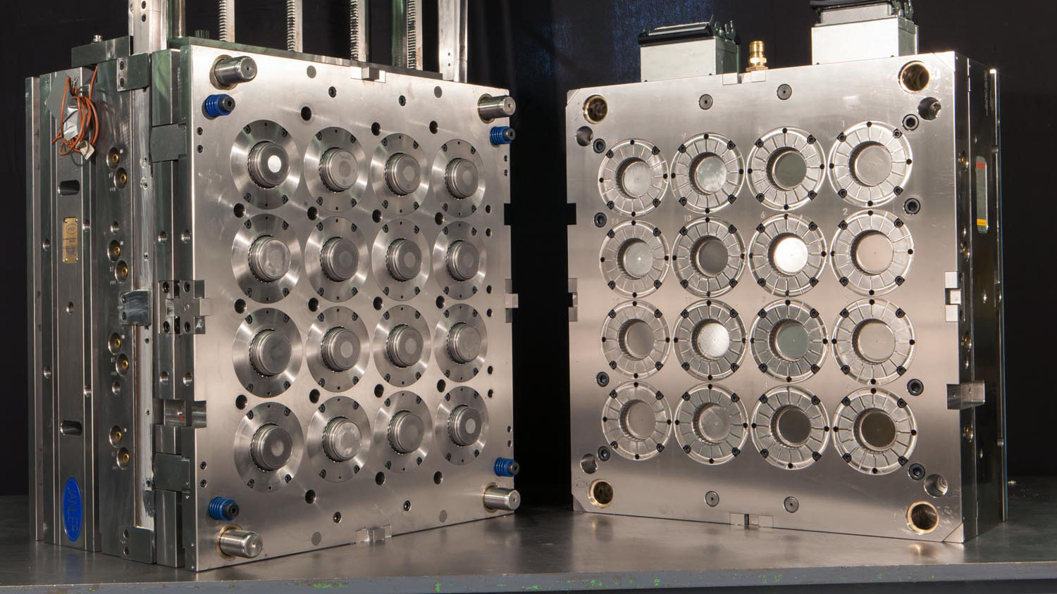
The first step to extending the mold’s service life successful is to choose the right mold structure. The structure of a mold should revolve around the pressure used during manufacture. Pressure should be evenly distributed across its surface during the manufacturing process, to reduce unnecessary stress concentration that might cause deformation or cracking. The principle of this is to make sure enough strength and stiffness is estimated, a reasonable decision of blanking clearance is made, and reduce stress concentration, to guarantee all gears of production meet the production standards.
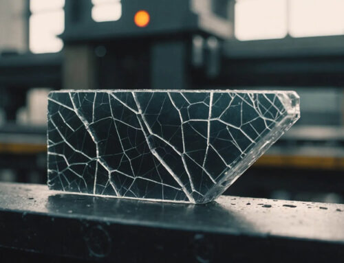
During the process of injection and die-casting, molds should endure repeated impacts, constant contact vibrations, frictions, and extreme pressure and temperature cycles. These conditions inevitably contribute to surface wear, gear fatigue, and, in some cases, catastrophic and irreversible fractures. To avoid maintenance costs, design the right molding structure with the help of professionals.

2. Applying the Correct Heat Treatment and Temperature Control
Incorrect heat treatment is one of the most common reasons for premature mold failure. According to the details of the article written by our research engineers here in KingStar Mold, approximately 45% of injections and die-casting molds lose their functionalities due to improper thermal management in total.
Effective temperature treatment techniques—such as annealing, quenching, and tempering at controlled high or low temperatures—help to optimize the mold’s internal microstructure or add an oxidated protection coating to the mold’s surfaces, enhancing toughness, and improving resistance to thermal fatigue. It is also important to keep a precise temperature control during operations, as uneven or extreme heat change can cause material degradation, resulting in shortening the service life of injection and die-casting molds. More technical details on these methods can be found and explained in the article.

3. Enhancing Mold Surfaces with Advanced Treatments
The surface of a mold determines the mold’s resistance to wear, friction, and corrosion, as a strong coating can prevent unnecessary damage. Proper surface treatment not only increases the mold’s hardness, but also improves their lubricating properties, and in general, their overall durability.
Among the most widely used surface enhancement techniques, here are some techniques explained in brief:
- TD (Thermal Diffusion): Strengthens surface layers through precipitation from exothermic reactions or diffusing, to create a harden layer of protection coating.
- CVD (Chemical Vapor Deposition): Adds evenly spread protective coatings with excellent adhesion by using chemical reactions in vapor.
- PVD (Physical Vapor Deposition): Creates thin, hard coatings with superior wear resistance, by physically spraying the surface with the molecules of gasified targeted materials, like ceramics and different metal.
These treatments greatly reduce the risk of surface related failures, ensuring a smoother production process and longer service life for your molds.

4. Ensuring Proper Lubrication
Lubrication can improve mold’s thermal stability and wear resistance, it plays a decisive role in extending the mold’s service life. A mold’s possible operating environment could be briefly summarized into three basic phases: The cooling phase (in low temperature), the working phase (in room temperature), and thermal transition phase (where temperature might change from heat to cold rapidly and periodically).
Inadequate or improper lubrication under these varying conditions can lead to corrosion, oxidative wear at moderate temperatures, and adhesive wear at higher temperatures.

Conclusion
Injection and die-casting molds is an investment, the lifespan of molds has direct and indirect impacts on the overall efficiency of the production process. It is an important decision that should be made by technical process designing professionals, just by choosing the right structure and materials, applying thermal treatments, enhancing surface durability, and maintaining effective lubrication, is far from enough. Manufacturers can learn more about extending their mold’s service life, from the comprehensive and detailed article that our research engineers prepared.
For longer-lasting molds, reliable products, and one simple, cost-saving workflow. Contact us at: sales@kingstarmold.com.