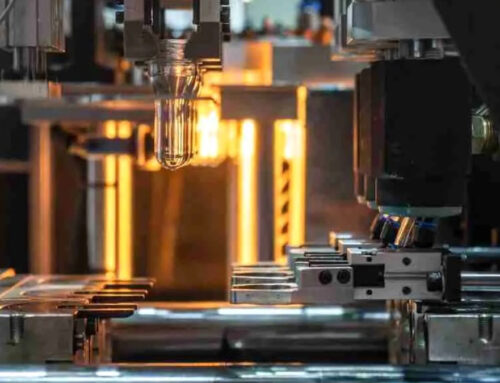
This plastic parts inspection specification applies to all plastic components produced by KingStar Mold, including those made through injection molding, as well as externally sourced plastic accessories and products made through secondary processing such as soft touch coating, screen printing, and painting. This document outlines the inspection standards and quality control guidelines used to evaluate product appearance, structure, and surface treatment. General plastic parts from other suppliers may also be inspected in accordance with these molded part inspection criteria to ensure consistent quality.
All relevant standards and components shall comply with the technical requirements on the drawings and the engineering samples. The normal single sampling plan shall follow ISO2859-1:1999 (see Appendix Tables 1 and 2). The relevant sampling standards or judgment criteria can be revised according to the quality status or customer requirements, etc.
II. Inspection Items
1. Visual Inspection
1.1 Defect Definitions
1.1.1 Specks (Containing Impurities): Appear as spot-like defects; thier size is determined by the maximum diameter. These include impurities of different colors or foreign particles mixed into the plastic which are exposed on the surface.
1.1.2 Flash (Burrs): Linear protrusions at the edges or bonding lines of plastic parts (usually caused by poor molding). Caused by excess material produced in the non-structural parts of the product.
1.1.3 Splay (Silver Streaks): The surface of the plastic part fades due to gas formed during molding (usually white). Most of these gases are the moisture of plastic particles. Some plastic particles absorb moisture, so a drying process should be added before manufacturing.
1.1.4 Bubbles: Circular protrusions on the surface caused by the isolation zones inside the plastic.
1.1.5 Deformation: Warping of plastic parts caused by internal stress differences or poor cooling during manufacturing.
1.1.6 Ejector White (Eject Marks): Whiteening and deformation of the finished product caused by the ejection from the mold, typically appearing on the opposite side of the ejector pin (usually the core side)
1.1.7 Short Shot: Insufficient material in a certain part of the product due to damage of the mold or other reasons.
1.1.8 Delamination: Caused by raw material contamination or foreign substances mixed in or different plastics mixed together.
1.1.9 Flow Marks: Wavy lines or streaks caused by the flow of molten plastic at the gate during molding.
1.1.10 Fusion Marks: Linear traces on the surface formed by the convergence of two or more molten plastic flows during molding which can be visually and tactilely felt.
1.1.11 Minor Scratches: Surface scratches or marks without depth (usually caused by manual operations).
1.1.12 Deep Scratches: Linear scratches on the surface caused by hard objects or sharp tools (usually caused by manual operations).
1.1.13 Sink Mark and Shrinkage: Dents on the surface or dimensions smaller than the designed size of the part (usually caused by poor molding). The local overall surface of the product sinks due to material contraction.
1.1.14 Color Streaks (Color Separation): Striped or spot-like color marks on the plastic production (usually caused by the addition of recycled materials).
1.1.15 Bruises and Dents: Traces caused by hard objects or sharp tools hitting the surface or edge of the product.
1.1.16 Oil Stains: Oily residue or marks on the part surface caused by mold release agents or contamination, often appearing glossy or streaky.
1.1.17 Poor Trimming: Irregular shapes such as gaps occur at the product edges due to manual trimming.
1.1.18 White Marks: Due to internal stress, white marks different from the original color produced on the product surface.
1.1.19 Blocked Hole (Flash Blockage): Areas meant to be open or transparent are sealed off by excess material (flash).
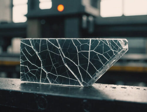
1.1.20 Crack (Fracture): Defects resulting from the partial disconnection of plastic parts.
1.1.21 Fibrils (Feathering): Fine filament-like material attached to the surface, caused by friction or shearing.
1.1.22 Adhesion: Uneven surface caused by molten plastic sticking to an overheated mold cavity.
1.1.23 Color Deviation: The color of the actual product differs from the approved sample or designated color code beyond the acceptable tolerance.
1.2 Defect Definitions (Secondary Processing Components)
1.2.1 Paint Particles: Areas where the coating thickness is thicker than the surrounding areas.
1.2.2 Sagging: Due to excessive local spraying, the coating droops and forms a strip-like shape.
1.2.3 Wrinkling: Wrinkles occur at the coating area due to poor leveling of the coating film.
1.2.4 Blurred Boundaries: Intersecting boundaries between different colored coatings.
1.2.5 Pinholes: Small holes formed due to the rupture of bubbles generated during spraying.
1.2.6 Missed Spray: Areas that were supposed to be sprayed but failed.
1.2.7 Uneven Coating: Areas with uneven coating thickness.
1.2.8 Foreign Particles: Indentations on the coating surface caused by dirt spots or dust.
1.2.9 Blushing (Whitening): A hazy, whitish appearance on the paint surface.
1.2.10 Bruises and Scratches: Linear depth marks on the part surface caused by hard objects or sharp tools (usually caused during manual operations).
1.2.11 Light Spray (Thin Coating): Areas where the coating is too thin and the base color of the substrate can be seen.
1.2.12 Discoloration, Double Printing, Tilting, Misalignment: White spots in the printed characters due to impurities or other reasons during printing.
1.2.13 Missing Printing: Printing that lacks strokes or corners, or where breaks in characters exceed 0.3 mm.
1.2.14 Fine Font Deviation and Uneven Ink: Uneven drying of ink and inconsistent printing force during printing.
1.2.15 Misprints, Wrong Characters and Illegible Silkscreen Text: Not in accordance with the sample.
1.2.16 Color Deviation: The product color deviates beyond the acceptable tolerance when compared with the approved sample or standard color code.
1.2.17 Air Streaks: Traces left by gases on the product surface that are different from the base color, shiny, and have a flowing appearance due to various reasons.
1.3 Inspection methods and requirements for appearance defects
1.3.1 Vision: Inspectors must have normal or corrected visual acuity of 1.0 or higher, with no color blindness.
1.3.2 Environmental lighting: Standard lighting without direct sunlight; when natural daylight is not available, illumination should be provided by a 100W cool white fluorescent lamp or a dedicated light inspection box.
1.3.3 Visual distance: The distance between the inspector’s eyes and the product should be 30–50 cm with the line of sight at an angle of 45 ± 15° to the surface of the object being inspected.
1.3.4 Observation time: <10 seconds (3 seconds are required for each visible plane)
1.3.5 For appearance inspection, inspector should use general-purpose measuring instruments.
1.3.6 Appearance inspection standards
1.3.6.1 Appearance inspection standards for plastic parts (inspection standards for injection molded parts are shown in Table 3)
1.3.6.2 Appearance inspection standards for secondary processed parts (inspection standards for secondary processed parts are shown in Table 4)
1.3.7 classification of defect-critical surfaces
A surface: The surface that can be seen during normal product operation (e.g., top cover, front end, interfaces)
B surface: The surface that is not often visible during normal product operation (e.g., side surfaces)
C surface: The surface that is not visible during normal product operation (e.g., bottom of the product)
D surface: Internal or non-exposed structural surfaces (e.g., internal walls, structural components inside the product)
1.3.8 Legend for A, B, C, and D Surface Classification

1.3.9 Requirements for appearance inspection of plastic parts: The product color should comply with the specified requirements, the colors should be consistent, the surface should be smooth, and there should be no defects such as bubbles, shrinkage cavities, scratches, burrs, impurities, etc.
1.3.10 Inspection requirements and methods for soft coating and painted plastic products (appearance of secondary processed parts)
1.3.10.1 The product color should comply with the specified requirements, the colors should be consistent, the surface should be smooth, the spraying should be complete, and there should be no defects such as flow marks, scratches, etc.
1.3.10.2 Adhesion test
1.3.10.2.1 Test conditions: Take an area of 4×4 cm2 on the surface and evenly divide it into small pieces of 1×1 mm2. Use tape to stick it for 30-90 seconds and then quickly pull the tape up.
1.3.10.2.2 Test equipment: Utility knife and adhesive tape.
1.3.10.2.3 Evaluation Criteria: If more than 15% of the painted area peels off at the grid edges or intersections, or if entire grid squares are removed, the part is considered defective.
1.3.10.3 Solvent Resistance Test
1.3.10.3.1 Test conditions: Use (alcohol, gasoline) to wipe the painted surface and let it stand for 3 minutes.
1.3.10.3.2 Evaluation Criteria: The appearance of the painted part should be able to resist the corrosion of the solvent for 3 minutes, without obvious layer cracking, blistering, wrinkling or potential decomposition of the paint.
1.3.10.4 Wear resistance: Use a sandcloth-covered grinding block (500g) to grind the part back and forth for 20 times. If there is no paint peeling or exposed base color, it is judged as qualified.
2. Stress Resistance Test
2.1 Steel Ball Impact Test: A 5kg iron ball freely falls from a height of 100cm and hits the machine shell. A part is considered qualified if no crushing damage occurs.
2.2 Torque Detection of Screw Holes:
2.2.1 For products with only one cavity number, 2-3 pieces are selected.
2.2.2 For products with two or more cavity numbers, 2 pieces should be selected for each cavity.
2.2.3 Use a torque screwdriver to fully screw and unscrew the self-tapping screws with the corresponding torque 10 times in both directions. There should be no slipping or whitening. (Torque is shown in Table 5)
2.3 Drop Test: For handheld machines, assemble the entire set of plastic parts and install the upper handle. It should be able to withstand 3 drops from a height of 1m to the ground. Each drop should be impacted at a different point. After the test, the plastic part must not exhibit any safety risks, functional failures, or significant visual defects.
3. Dimension Inspection
3.1 Housing Dimension Inspection
3.1.1 The stator slot and brush holder slot should be inspected using standard gauge blocks (qualified stators and brush holders are assembled for inspection), with appropriate tightness. The misalignment of the bearing chamber and the left and right housings should not exceed 0.3mm. The sampling method is to select 2-3pcs from each batch of products, with only one cavity number selected. For products with two or more cavity numbers, 2pcs should be selected from each hole.
3.1.2 For machines that can rotate 180°, the handle should be able to rotate 180° without the use of tools, but 360° rotation is not allowed.
3.1.3 Inspect housing fit using the rear cover; the misalignment must not exceed 0.3 mm.
3.2 Rear Cover Dimension Inspection
3.2.1 The shell is assembled for inspection, with the misalignment of the rear cover not exceeding 0.3mm. The sampling method is to select 2-3pcs from each batch of products, with only one hole number selected. For products with two or more hole numbers, 2pcs should be selected from each hole.
3.3 Handle and Handle Cover
3.3.1 Perform assembly check with qualified matching internal parts; the fit should be moderate.
3.3.2 The switch handle and handle cover should be flush when closed, with misalignment not exceeding 0.3 mm.
3.3.3 For machines that can rotate 180°, the shell should be able to be assembled without the use of tools to achieve 180° rotation, but 360° rotation is not allowed.
3.3.4 The sampling method: 2–3 pcs for one cavity number, or 2 pcs per cavity if multiple cavity numbers.
3.4 Small Plastic Part Dimension Inspection
3.4.1 Inspect according to technical drawings or engineering samples.
3.4.2 The threads are inspected using thread gauges. The go gauge must engage smoothly; the no-go gauge must not pass.
3.4.3 For the phenolic router baseplate and its mount, the misalignment must not exceed 0.8 mm.
3.4.4 The stator and rotor insulation sheets should be visually inspected to ensure that the slot shape is consistent with the iron core
3.4.5 For fan blades, check the inner flat, thickness, and outer diameter. Use plug gauges to measure radial and end-face dimensions after assembly.
III. Sampling Standards, Judgement Criteria and Defect Classification
1. Sampling Standards
Sampling for plastic products, outsourced plastic components, and secondary processed parts (soft spraying, screen printing, painting) shall be conducted at Special Inspection Level S-4: Critical defects: AQL = 0; Major defects: AQL = 1.5; Minor defects: AQL = 4.0
2. Judgement Criteria
2.1 Classified by the severity of defects into critical defects, main defects, and secondary defects.
2.2 Critical defects refer to those that endanger consumer safety, meaning they may have dangerous and unsafe factors; main defects refer to all defects that weaken the product’s performance, functionality, or damage the normal appearance of the goods; secondary defects refer to those that do not reduce the product’s specified performance or are related to the expected appearance of the product.
3. Defect Classification (Defect Classification Table 6)
IV. Packaging Requirements
1. Packaging must comply with specified requirements and must not exhibit any defects that could affect product protection or result in missing components.
2. The packaging method must comply with the specified requirements.
V. Note
Only products that pass all of the above inspections shall be marked with a pass label by the inspector and then transferred to the next process step. Non-conforming products must be handled in accordance with the Non-Conforming Product Control Procedure.
VI. Appendix
1. Table 1 Sample Quantity Code
2. Table 2 Normal Inspection One-time Sampling Scheme (Main Table)
3. Table 3 Injection Mold Inspection Standards
4. Table 4 Secondary Processing Component Inspection Standards
5. Table 5 Screw Hole Torque
6. Table 6 Defect Classification
| Batch | Special Inspection Level | General Inspection Level | |||||
| S-1 | S-2 | S-3 | S-4 | I | II | III | |
| 2~8 | A | A | A | A | A | A | B |
| 9~15 | A | A | A | A | A | B | C |
| 16~25 | A | A | B | B | B | C | D |
| 26~50 | A | B | B | C | C | D | E |
| 51~90 | B | B | C | C | C | E | F |
| 91~150 | B | B | C | D | D | F | G |
| 151~280 | B | C | D | E | E | G | H |
| 281~500 | B | C | D | E | F | H | J |
| 501~1200 | C | C | E | F | G | J | K |
| 1201~3200 | C | D | E | G | H | K | L |
| 3201~10000 | C | D | F | G | J | L | M |
| 10001~35000 | C | D | F | H | K | M | N |
| 35001~150000 | D | E | G | J | L | N | P |
| 150001~500000 | D | E | G | J | M | P | Q |
| 500001 and above | D | E | H | K | N | Q | R |
Table 1 Sample Quantity Code (ISO2859-1:1999)
 ( ISO2859-1 1999)")
Table 2 Normal Inspection One-time Sampling Scheme (Main Table) ( ISO2859-1:1999)
| No. | Category Defect | Plastic Part | Soft Spray and Coating |
|---|---|---|---|
| 1 | Specks | Surface A: Max 2 dots ≤∮0.4mm and 4 dots ≤∮0.2mm within Ø100mm area, minimum 45mm apart. Total not exceeding 4 on same surface. Surface B: Max 3 dots ≤∮0.6mm and 4 dots ≤∮0.4mm within Ø100mm area, 45mm apart. Total not exceeding 4. | No specific requirements (must be fully covered after painting) |
| 2 | Flash / Burrs | No burrs allowed on vents or through holes. On parting lines, flash ≤0.3mm is acceptable if it does not affect functionality. | Same as injection molded parts |
| 3 | Splay (Silver Streaks) | Surface A: Not allowed. Surface B: Within Ø100mm, max 2 pcs 0.5×5mm and 3 pcs 0.5×3mm, ≥45mm spacing, total not exceeding 4. Surface C: Not obvious ones allowed. Surface D: Must not affect functionality. | No specific requirements (must be fully covered after painting) |
| 4 | Bubbles | The A and B surfaces must not have any obvious tactile bubbles. Max 3 visible bubbles within <10mm spacing. | Allowable if sandable and paintable |
| 5 | Deformation | Max warpage/flatness deviation ≤2mm within 100mm range (specific PP material requirements apply). | Same as injection molded parts |
| 6 | Ejector White (Eject Marks) | Surface A: Not allowed. Surface B, C: Not obvious ones allowed. | No specific requirement (must be fully covered after painting) |
| 7 | Short Shots | Allowed only on non-visible surfaces if functionally unaffected. | Same as injection molded parts |
| 8 | Delamination | A and B surfaces are not allowed, while C surface allows for an imperceptible layering. | Same as injection molded parts |
| 9 | Flow Marks | Slight flow marks allowed. | No specific requirement (must be fully covered after painting) |
| 10 | Weld Lines | Length ≤ 1/3 of flow direction, depth must not catch fingernail. | Same as injection molded parts |
| 11 | Minor Scratches | Surface A: Max 1 scratch 0.1×5mm, or 2 scratches 0.2×3mm within Ø100mm, 45mm apart. Max 2 per surface. Surface B: Max 2 scratches 0.2×6mm or 3 scratches 0.2×3mm within Ø100mm, 45mm apart. Max 3 per surface. Surface C: No obvious impact. Surface D: Must not affect functionality. | Not allowed if visible through paint |
| 12 | Deep Scratches | Any scratch ≥10mm in length or ≥0.1mm in width is not allowed. | Not allowed if not covered by paint |
| 13 | Sink Mark and Shrinkage | Surface A: Max 1 dent ≤∮3mm and ≤1mm deep. Surface B, C: Max 2 minor dents, not obvious. Surface D: Must not affect functionality. | Same as injection molded parts |
| 14 | Color Streaks (Color Separation) | Surface A, B: Not allowed. Surface C: Slight color swirl allowed. | No specific requirement (must be fully covered after painting) |
| 15 | Bruises and Dents | Surface A, B: Not allowed Surface C: Slight dents acceptable | No specific requirement (must be fully covered after painting) |
| 16 | Oil Stains | Slight oil stains acceptable | No specific requirement (must be fully covered after painting) |
| 17 | Poor Trimming | Surface A, B: Not allowed | Same as injection molded parts |
| 18 | White Marks | Surface A: Not allowed Surface B, C: Slight white marks acceptable | No specific requirement (must be fully covered after painting) |
| 19 | Blocked Hole (Flash Blockage) | Not allowed | Same as injection molded parts |
| 20 | Cracks / Fractures | Localized tearing allowed on internal, non-functional surfaces | Same as injection molded parts |
| 21 | Fibrils (Feathering) | Not allowed on visible surfaces | Same as injection molded parts |
| 22 | Adhesion | Surface A, B: Not allowed | No specific requirement (must be fully covered after painting) |
| 23 | Color Deviation | Obvious color shift (more than ±1 level from standard color number) not allowed | No specific requirement (must be fully covered after painting) |
Table 3 Injection Mold Inspection Standards
| No. | Category Defect | Soft Touch Coating / Painting / Silk Screen Printing | Notes |
|---|---|---|---|
| 1 | Paint Particles | Surface A: Within a 100 mm diameter area, allow up to 2 particles with ∮≤0.4 mm and 4 particles with ∮≤0.2 mm; the distance between any two particles must exceed 45 mm. The total number of particles on the same surface must not exceed 4. Surface B: Within a 100 mm diameter area, allow up to 2 particles with ∮≤0.6 mm and 4 particles with ∮≤0.2 mm; spacing between particles must exceed 45 mm. Total count must not exceed 4. Surface C: No obvious visual impact. | |
| 2 | Sagging | Not allowed on surfaces A, B, or C. | |
| 3 | Wrinkling | Not allowed on surfaces A, B, or C. Slight wrinkles are acceptable on non-visible (hidden) surfaces. | |
| 4 | Blurred Boundaries | Due to tooling limitations, slight color blending within 0.2 mm at the paint boundary is acceptable. | |
| 5 | Pinholes | Surface A: Within a 100 mm diameter area, allow up to 2 pinholes with ∮≤0.3 mm and 3 with ∮≤0.2 mm; spacing between defects must exceed 45 mm. Total not to exceed 4. Surface B: Within a 100 mm diameter area, allow up to 2 pinholes with ∮≤0.4 mm and 3 with ∮≤0.2 mm; spacing above 45 mm. Max total: 4. Surface C: No obvious visual impact. | |
| 6 | Missed Spray | Not allowed on surfaces A, B, or C. | |
| 7 | Uneven Coating | Not allowed on surfaces A, B, or C. Surface D: Allowed if not affecting functionality. | |
| 8 | Foreign Particles | Surface A: Within a 100 mm diameter area, allow up to 2 particles measuring 0.1×3 mm and 4 particles of 0.1×1 mm; spacing must exceed 45 mm. Total must not exceed 4. Surface B: Within a 100 mm diameter area, allow up to 2 particles of 0.1×5 mm and 3 of 0.1×3 mm; spacing over 45 mm. Total not to exceed 4. Surface C: No obvious visual impact. | |
| 9 | Blushing (Whitening) | Not allowed on surfaces A, B, or C. | |
| 10 | Bruises and Scratches | Surface A: Within a 100 mm diameter area, allow 1 scratch of 0.1×5 mm or 2 scratches of 0.2×3 mm; spacing above 45 mm. Total scratches not to exceed 2. Surface B: Within a 100 mm diameter area, allow 2 scratches of 0.2×6 mm or 3 of 0.2×3 mm; spacing over 45 mm. Total scratches not to exceed 2. Surface C: No obvious impact. Surface D: Allowed if not affecting functionality. | |
| 11 | Light Spray (Thin Coating) | Slight lightspray is allowed on non-visible surfaces. | |
| 12 | Discoloration | Not allowed | |
| 13 | Missing Printing | Not allowed | |
| 14 | Fine Font Deviation | Font deviation ≥ 0.2 mm is not allowed | |
| 15 | Misprints | Not allowed | |
| 16 | Color Deviation | Significant color variation is not allowed (i.e., deviation exceeding ±1 level from the standard color reference) | |
| 17 | Air Streaks | Not allowed |
Table 4 Secondary Processing Component Inspection Standards
| The nominal diameter of the thread | Torque N.m |
|---|---|
| D≤2.8 | 0.4 |
| 2.8 | 0.5 |
| 3.0 | 0.6 |
| 3.2 | 0.8 |
| 3.6 | 1.2 |
| 4.1 | 1.8 |
| 4.7 | 2.0 |
| D>5.3 | 2.5 |
Table 5 Screw Hole Torque
| Plastic Parts | Defect Type | Critical | Secondary | Primary |
| 1 | Specks (Impurities) | √ | ||
| 2 | Flash (Burrs) | √ | ||
| 3 | Silver Streaks / Oil Stains | √ | ||
| 4 | Bubbles | √ | ||
| 5 | Deformation | √ | ||
| 6 | Ejector Marks (Whitening) | √ | ||
| 7 | Short Shot | √ | ||
| 8 | Delamination | √ | ||
| 9 | Flow Marks / Weld Lines | √ | ||
| 10 | Scratches / Dents | √ | ||
| 11 | Sink Marks | √ | ||
| 12 | Poor Trimming | √ | ||
| 13 | White Marks | √ | ||
| 14 | Cracks | √ | ||
| 15 | Blocked Holes | √ | ||
| 16 | Fibrils (Feathering) | √ | ||
| 17 | Color Deviation | √ | ||
| 18 | Adhesion | √ | ||
| 19 | Color Separation | √ | ||
| 20 | Loose Stator | √ | ||
| 21 | Stress Crack Resistance | √ |
Table 6-1 Defect Classification-Plastic Parts
| Secondary Option | Defect Type | Critical | Secondary | Primary |
|---|---|---|---|---|
| 1 | Paint Particles | √ | ||
| 2 | Sagging | √ | ||
| 3 | Pinholes | √ | ||
| 4 | Wrinkling | √ | ||
| 5 | Air Threads | √ | ||
| 6 | Missing Coating (Overspray) | √ | ||
| 7 | Blurred Boundaries | √ | ||
| 8 | Light Spray (Low Coverage) | √ | ||
| 9 | Uneven Coating | √ | ||
| 10 | Whitening | √ | ||
| 11 | Foreign Particles (Dust, Fibers) | √ | ||
| 12 | Scratches | √ | ||
| 13 | Color Deviation | √ | ||
| 14 | Missing / Double / Fuzzy Print | √ | ||
| 15 | Font Detail Deviation | √ | ||
| 16 | Blurred Silk Screen Text | √ | ||
| 17 | Air Streaks | √ | ||
| 18 | Poor Coating Adhesion | √ | ||
| 19 | Misprint / Wrong Characters | √ | ||
| 20 | Loose Stator | √ | ||
| 21 | Stress Crack Resistance | √ |
Table 6-2 Defect Classification-Secondary Option