That moment when a perfectly designed sheet metal component fails – not due to the metal itself, but because an integrated nut strips, a clip snaps, or a mounting point misaligns during assembly or use – is more than frustrating; it highlights a critical oversight. Successfully embedding hardware (fasteners, studs, clips, brackets) into sheet metal is far more than a final assembly step; it’s a fundamental design and operational challenge impacting structural integrity, functional reliability, manufacturing efficiency, and overall cost.
Achieving seamless integration demands a holistic approach, spanning from initial material selection and compatibility checks, through rigorous adherence to minimum thickness constraints and careful hardware selection matched to manufacturing processes like stamping, bending, and welding, down to the precise specification of design elements like hole diameters, thread types, and counterbore/countersink geometries. Furthermore, the choice of insertion method and its impact on installation time, alongside proactive strategies to avoid common pitfalls encountered in production and operation, are all essential components of the process.
This guide dives deep into these interconnected practicalities, equipping you with the knowledge to design and execute robust, efficient, and reliable hardware integration in sheet metal from the ground up.
When choosing hardware, the first thing to consider is on which material the hardware is installed. It’s crucial to consider the properties of both the sheet metal and the hardware, ensuring compatibility for seamless integration. This brings us to the first question: What materials are commonly used for sheet metal parts and the hardwares attached to them?
The selection of materials is the key to achieving successful integration of sheet metal metal components. The compatibility between sheet metal materials, components, and the expected usage environment directly affects their service life, functionality, and manufacturability. The following are the common choices and their key influencing factors:
- Stainless Steel: Offers exceptional corrosion resistance critical for harsh environments (chemical exposure, moisture, high temps). Its high strength-to-weight ratio and durability make it ideal for demanding applications like food processing equipment, medical devices, and automotive components. Polished finishes maintain aesthetics well, but machining/work hardening can be considerations.
- Aluminum: Valued for its lightweight nature and inherent corrosion resistance (forming a protective oxide layer). While not as strong as stainless steel, its excellent formability and machinability make it popular in aerospace, automotive body panels, and electronics enclosures where weight savings are paramount. Surface treatments (anodizing) can further enhance properties.

Steel (Cold Rolled & Galvanized):
- Cold Rolled Steel (CRS): Provides superior surface finish, tighter dimensional tolerances, and increased strength compared to hot-rolled. Excellent for precision parts, enclosures, and brackets requiring good weldability and a smooth surface for painting or plating. Vulnerable to corrosion without coating.
- Galvanized Steel: Features a zinc coating (hot-dip or electroplated) for enhanced corrosion resistance, essential for outdoor structures, HVAC systems, and automotive underbodies. Offers the core strength of steel at a lower cost than stainless, though welding requires specific techniques to avoid damaging the zinc layer.
Copper & Brass:
- Copper: Chosen primarily for its unmatched electrical and thermal conductivity, alongside good corrosion resistance. Common in electrical components, busbars, heat exchangers, and roofing. Develops a protective patina over time. Softer, requiring careful handling.
- Brass (Copper-Zinc Alloy): Offers better machinability and strength than pure copper, good corrosion resistance, and a distinctive gold-like aesthetic. Widely used for decorative hardware, plumbing fittings, electrical terminals, and instruments. Conductivity is lower than copper.
1.2 Compatibility with Hardware
The material chosen for sheet metal parts should be compatible with the hardware used in the design. Hardware can include fasteners, rivets, nuts, bolts, washers, and specialized components such as clinch nuts or PEM hardware. Here’s why compatibility matters:
- Strength of Hardware and Material: The hardware selected should be able to engage securely with the material without compromising the sheet metal. For instance, soft metals like aluminum may require specially designed fasteners, such as self-tapping screws, that can create strong threads without causing material deformation. Stainless steel, on the other hand, may support more robust fastening options like rivets or bolts.
- Thread Compatibility: When using threaded fasteners, the material must be able to hold the threads firmly. Materials like steel and stainless steel have the necessary hardness to accept threaded fasteners without thread stripping, whereas softer materials like aluminum or copper might require thread inserts or specific fastener designs to prevent damage.
- Corrosion Resistance Considerations: It’s crucial to match the material’s properties with the type of hardware used, particularly in environments prone to corrosion. For example, combining aluminum with stainless steel hardware can result in galvanic corrosion, where the two metals react and deteriorate over time. In such cases, selecting materials that are both resistant to corrosion or using coatings can help mitigate this issue.
So here is a compatibility-driven combinations table and critical exclusion rationale for your reference:
| Base Material | Fasteners & Inserts | Hinges/Bearings | Conductive Hardware | Critical Exclusions |
| Cold-Rolled Steel | Zinc-plated steel | Powder-coated steel | Tin-plated steel springs | Copper alloys (ΔV > 0.5V) |
| Aluminum 5052 | SS304 + PTFE-coated washer | Anodized aluminum | Beryllium copper clips | Uncoated steel |
| Stainless Steel | SS316 | SS304 + PTFE film | Nickel-plated brass | Aluminum fasteners |
| Copper C110 | Phosphor bronze | Self-lubricating bronze | Silver-plated copper | Steel (unless nickel-plated) |
| Brass C360 | Silicon bronze | IGUS® polymer bearings | Beryllium copper | Aluminum/plain steel |
- Steel hardware on copper/brass: Prohibited without barrier plating due to severe galvanic corrosion (ΔV >0.4V in seawater).
- Aluminum contacts: Forms insulating Al₂O₃ layer → contact resistance instability.
- Zinc die-cast components: Creep risk at >80°C with brass substrates.
2. Minimum Part Thicknesses
Selecting the appropriate sheet metal thickness isn’t just about part strength; it’s the bedrock of successful hardware integration. Insufficient thickness directly jeopardizes both the hardware’s function and the part’s structural integrity, often leading to premature failure. Here’s why thickness is non-negotiable and the critical thresholds to consider:
2.1 Impact on Hardware Engagement

2.1.1 Securing Hardware Engagement:
- Threaded Fasteners (Screws, Tapped Holes):Material thickness must exceed 1.5 times the fastener diameter to ensure adequate thread engagement depth. For example, using an M4 screw (4mm diameter) requires at least 6mm of engaged material thickness. Falling short risks stripped threads and pull-out failure under load. Thin sheets often force reliance on less robust methods like self-clinching nuts or weld nuts.

- Rivets (Blind & Solid):Requires sufficient material to form a proper “bucktail” (deformed end). Standard rivets generally demand a minimum material thickness of 1.0 mm (0.040″). Below this, the rivet cannot deform the material effectively, resulting in weak, unreliable joints prone to vibration failure.

- Countersunk Fasteners (Screws/Rivets):Needs enough depth for the conical head to sit flush without protruding or weakening the opposite side. As a rule, material thickness should be at least equal to the head height of the countersunk fastener. Thinner material risks “bottoming out,” preventing proper clamping, damaging the backside surface, or creating stress points that crack the whole sheet.
2.1.2 Maintaining Structural Integrity (Beyond the Fastener)
Thin sheets buckle and deform easily under load.
- Bending & Warping:Panels below recommended thickness for their span and load (e.g., < 1.2 mm for unsupported brackets under moderate stress) can deflect excessively or permanently deform during handling or operation.
- Vibration & Fatigue Failure:Dynamic environments demand robustness. Thin sections (especially below 0.8 mm) are highly susceptible to fatigue cracking initiated at hardware mounting points under cyclic stresses (e.g., engine mounts, vibrating machinery guards).
- Point Load Failure:Hardware attachment points concentrate stress. A load-bearing bracket mounted on overly thin sheet (g., a 100N load on a 1.0mm thick steel bracket without reinforcement) can tear out or deform catastrophically.
2.1.3 The Critical Balance: Thickness vs. Cost/Weight
While thicker material boosts strength and hardware options, it increases weight and material cost significantly.
- Cost Impact:Increasing thickness from 1.5mm to 2.0mm steel can raise material costs by 25-35%.
- Weight Impact:Aluminum at 2.0mm weighs ~40% less than steel at the same thickness, but achieving equivalent strength might require thicker aluminum sections, partially offsetting the savings.
- Optimization Goal:The design challenge is to select the minimum thickness that simultaneously satisfies:
-
- Hardware engagement requirements (see thresholds above).
- Structural demands (static loads, dynamic/vibration resistance).
- Weight targets.
- Cost constraints.
- Manufacturability (forming, bending limits).
However “the thicker the material, the better” is not the deal. Although thicker materials usually do have higher strength and durability, there is often a trade-off in terms of cost and weight and that’s why the balance between these factors needs to be found.
3. Hardware Selection
Then finally, here we are – the topic of today’s article – the selection of hardware. Choosing the right hardware for sheet metal parts is a critical step in ensuring the overall functionality, durability, and efficiency of the final product. It involves more than just picking the right screws or rivets; it’s about understanding how the hardware interacts with the sheet metal, its application, and its intended environment. The selection of materials for the hardware has been explained in the previous section. Now, let’s move on to the types of hardware and the installation methods.
3.1 Choosing the Right Hardware Type
Not all hardware is suitable for every sheet metal application. The first step in selecting the appropriate hardware is understanding the different types available and how they perform in various scenarios.
3.1.1 Self-Clinching Hardware

Self-clinching hardware is designed for easy installation into thin sheet metal. These fasteners are pressed into a pre-punched hole, where they clinch into place, creating a strong and permanent bond without the need for threading or additional components.
Benefits for Thin Sheet Metal:
- The automatic-locking (or self-clinching) fasteners are particularly suitable for materials that are too thin to accommodate traditional threads. This method provides a sturdy solution without compromising the integrity of the sheet metals.
- These fasteners do not require installation on both sides of the component, making them ideal for confined space environments.
Common Types:

- Nuts: Self-clinching nuts provide strong threads in thin metal, offering the advantage of reusable threads, which are ideal for fastening bolts or screws in assembly.

- Studs: Self-clinching studs offer permanent, strong attachment points for nuts, bolts, or other components.

- Standoffs: These are used to create a fixed distance between parts, useful in applications where parts need to be spaced out.
3.1 2 Captive Nuts

Captive nuts are another popular choice for hardware integration in sheet metal, offering simplicity and reliability.
Advantages in Accessibility and Ease of Use:
- Captive nuts are held securely in place by the surrounding material, ensuring that they won’t move during installation. This eliminates the need for a separate tool to hold the nut while threading a bolt.
- These fasteners are designed for ease of installation in tight or hard-to-reach spaces, making them ideal for applications where accessibility is a concern.
Applications in Automotive and Electronics:
- In the automotive industry, captive nuts are used to fasten body panels and interior components, providing a quick and reliable connection that can be easily disassembled for repairs.
- In electronics, they are used to mount circuit boards, panels, and other components, where ease of installation and removal is essential for maintenance and upgrades.
3.1.3 Rivets and Fasteners

Rivets are a staple of permanent assemblies, providing a strong and secure connection that’s difficult to undo.
They are commonly used in metal sheet components that require permanent and secure connections. This makes them highly suitable for environments with high stress or situations where disassembly is not necessary because once installed, the rivets cannot be removed unless damaging the material.
Apart from durability, rivets are a favorite in high-volume production due to their speed and efficiency in assembly because they require little setup and can be installed quickly.
3.1.4 Weld Nuts and Other Threaded Inserts

When you need strong, permanent threads in sheet metal, weld nuts and threaded inserts are often the best solution.
When to Use for Robust Threads in Sheet Metal:
- Weld nuts are used when you require a high-strength threaded connection that can withstand significant loads. These are ideal for situations where other hardware types might not provide sufficient resistance to pull-out forces.
- Threaded inserts, such as PEM nuts, are ideal for thinner materials where traditional threading may be impractical. They allow for strong, reusable threads and provide a secure attachment point for bolts and screws.
Comparison with Other Methods:
- While captive nuts and self-clinching hardware offer quick and easy installation, weld nuts provide stronger, more durable threads that are perfect for applications requiring long-term reliability.
- Compared to riveting, threaded inserts offer the added benefit of disassembly without compromising the strength of the connection.
3.2 Application-Specific Hardware Selection
Beyond the design, understanding the application of the sheet metal part helps refine the hardware selection process. Different environments, stresses, and functions require specific hardware characteristics.
- Corrosion Resistance: For parts used in outdoor or corrosive environments, such as marine or industrial applications, selecting hardware made from corrosion-resistant materials like stainless steel or aluminum is essential.
- Vibration Resistance: If the sheet metal part is used in a high-vibration environment (e.g., automotive or machinery), hardware like lock nuts or spring washers should be considered to prevent loosening over time.
- Load Requirements: Heavy-duty applications require stronger hardware materials, such as high-strength steel or titanium, while lighter applications may be suitable for aluminum or zinc-plated fasteners.
By considering the end-use environment, the correct hardware can be selected to ensure long-term reliability and performance. Yes, both the material and the type need to be taken into consideration. Here, only three aspects that need to be considered are listed, along with some feasible options (not all aspects, and not necessarily the only choices available).
3.3 Ensuring Compatibility with Manufacturing Processes
| Hardware Type | Suitable Process | Force/Tooling Requirements | Material-Specific Constraints |
| Self-Clinching PEM® | Press-fitting (stamping press) | 2–5 tons force | Steel: Min thickness = 0.8× flange Ø Aluminum: Min hardness H32 |
| Weld Nuts | Projection welding | 8–12 kA, 0.3–1.2 sec cycle | Zinc-coated steel: Requires pre-weld grinding Stainless steel: Use pulsed DC |
| Threaded Inserts | Thermal insertion/Ultrasonic | 200–400°C (thermal) 20 kHz (ultrasonic) |
Brass: Max temp 150°C → Prefer ultrasonic Copper: Requires oxidation-preventive gas |
| Adhesive-Bonded | UV-cure/Epoxy application | 30–90 sec cure time | Copper/Brass: Needs acidic primer (e.g., Loctite 770) |
This is merely providing a quick reference for your selection, and the installation methods mentioned therein will be elaborated in Section “Hardware Insertion Methods”.
And there’s automation compatibility: For high-volume production, selecting hardware that can be easily integrated into automated processes is important. For instance, self-clinching hardware can be inserted quickly with minimal human intervention, reducing production costs.
4. Hardware Requirements
When integrating hardware into sheet metal parts, the design must accommodate the specific needs of each hardware type. This section provides an overview of the critical elements involved in hardware installation, special considerations for hardware like clinch nuts, and the importance of adhering to installation guidelines to ensure optimal performance.
4.1 Key Design Elements for Hardware Installation
4.1.1 Hole Sizes
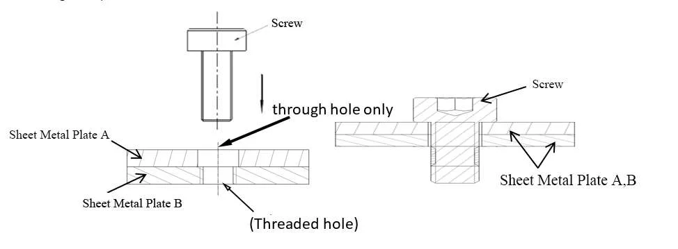
Proper hole sizing is crucial for the correct engagement of hardware. Holes must be precisely measured to match the dimensions of the hardware being installed. Too large a hole can result in a loose fit, while too small a hole can prevent hardware from being installed or cause damage during the insertion process.
Tip: Always refer to the hardware manufacturer’s specifications to determine the precise hole size for screws, bolts, or rivets. For instance, the hole diameter for a screw should typically be 1-2 mm larger than the screw’s diameter to allow for proper engagement without causing stress on the surrounding material.

4.1.2 Thread Types
The thread type is another key consideration when designing parts for hardware installation. Different hardware components require different thread types to ensure a secure connection. For example, screws may require metric or imperial threads, and the material into which the threads are cut must be able to handle the load and force placed on them.
Tip: Always verify the correct thread type and pitch needed for the hardware you are installing. Mismatched threads can result in weak or unreliable connections, which may lead to part failure.

4.1.3 Rivet Materials
Rivets, which are commonly used in sheet metal assemblies, must be selected based on both the material of the part and the rivet itself. Rivets are typically made of materials like aluminum, steel, or copper. The rivet material must be harder than the sheet metal to ensure proper crimping and a secure hold.
Tip: Ensure that the rivet material is compatible with the sheet metal to avoid issues like corrosion or insufficient crimping. For example, aluminum rivets should not be used with aluminum sheet metal to prevent galvanic corrosion.

4.2 Special Considerations for Clinch Nuts and Other Hardware
Clinch nuts and other specialized hardware require additional attention during the design phase. Clinch nuts, which are used to create a strong threaded connection in thin sheet metal, must be installed with care to ensure that they engage correctly without damaging the surrounding material.
- Installation Direction: The load direction for clinch nuts must be considered, as improperly oriented nuts can result in weak connections or failure under stress.
- Sheet Metal Thickness: Clinch nuts are designed for specific material thicknesses. Too thin a material can lead to an inadequate grip, while too thick a material may result in difficulty during installation.
Tip: Always check the installation guidelines for clinch nuts and other special hardware to ensure they are used within their specified tolerances.
Proper hole sizing is crucial for the correct engagement of hardware. Holes must be precisely measured to match the dimensions of the hardware being installed. Too large a hole can result in a loose fit, while too small a hole can prevent hardware from being installed or cause damage during the insertion process.
4.3 Importance of Following Installation Guidelines for Special Hardware
For special hardware like clinch nuts, PEM fasteners, or custom-designed parts, following the manufacturer’s installation guidelines is essential for ensuring long-term reliability and performance. These hardware types often have specific installation steps that, if not followed correctly, can lead to improper engagement, part damage, or failure.
Tip: When using non-standard or special hardware, take the time to review and understand the manufacturer’s recommendations for installation and handling. Ignoring these guidelines can result in costly repairs, production delays, or safety risks.
5. Countersinks and Counterbores
Countersinks and counterbores are crucial features for integrating hardware into sheet metal parts, particularly when the goal is to ensure smooth, flush installations and prevent hardware from protruding. Understanding when and how to incorporate these features can significantly impact both the appearance and functionality of the final product.

5.1 Countersinks
Countersinks are conical-shaped recesses that allow the head of a screw or rivet to sit flush with or below the surface of the sheet metal. This is often required for aesthetic reasons or to avoid sharp edges that could be a safety hazard. Proper countersinking is critical, as an improper angle or depth can affect the screw’s engagement and overall performance.
Key Considerations:
- The angle of the countersink should match the angle of the screw or rivet head, commonly 82° for standard screws or 90° for certain rivets.
- The depth should be sufficient to allow the hardware to sit flush but not so deep that it weakens the material around the hole.
5.2 Counterbores
Need that bolt head perfectly recessed? Forget just drilling a hole – you need a counterbore. This machined pocket gives flat-headed fasteners (bolts, nuts, washers) a place to sit flush. Unlike the angled cut of a countersink for screws like flat-heads, counterbores have flat bottoms for square-shouldered hardware.
Why Bother?
Protruding fastener heads snag on everything, mess up alignment in assemblies, and look unprofessional. Counterbores solve this – but only if you design them right. Get it wrong, and you weaken the part or wreck your tooling.
Designing Counterbores That Work:
- Diameter:
Don’t match the head size. Add at least 0.5mm (0.020″) clearance per side over the fastener head/washer diameter. Why?- Tolerances stack up (hole position, head size).
- Prevents jamming during assembly, especially with paint or plating.
- Example: A 10mm bolt head needs a ≥11mm counterbore.
- Depth: The Goldilocks Zone
Too shallow? The head sticks up. Too deep? You risk punching through or leaving tissue-paper-thin material underneath that buckles under load.- Target: Head height + just enough clearance (think 0.05-0.15mm / 0.002″-0.006″).
- Hard Rule: Never exceed 75% of the sheet thickness under the counterbore in critical areas. For a 2mm sheet, max depth is 1.5mm. Deeper = gamble on failure.
Spacing Rules: Where You Put It Matters as Much as How You Cut It
Placing counterbores (or countersinks) too close to edges, bends, or each other is a classic rookie mistake. It leads to cracked parts during bending, blown-out edges during punching, or weak spots that fail in service. These aren’t suggestions – they’re hard-won shop floor rules based on material thickness (T):
| From This… | To This… | Keep At Least This Far | Why? (The Real-World Consequence) |
| Counterbore Edge | Sheet Edge | 4 × T | Stops the edge tearing off like cheap cardboard during punching or under shear load. |
| Counterbore Center | Bend Line (Start) | 4 × T + Bend Radius | Prevents warping/cracking in the bend; gives the die space to work. Forget the radius? Expect a deformed mess. |
| Counterbore Center | Another Counterbore | 8 × T | Avoids creating a Swiss cheese weak spot between holes. Less material = less strength. |
| Countersink Edge | Sheet Edge | 4 × T | Prevents the thin lip at the edge splitting during forming or assembly. |
| Countersink Center | Bend Line (Start) | 3 × T | Countersinks near bends LOVE to crack – this is the minimum safety buffer. |
| Countersink Center | Another Countersink | 8 × T | Ensures enough meat between those conical cuts so they don’t collapse into each other. |
Why Ignoring Spacing Costs Money:
- Cracked Parts: Violate edge/bend distances? Hear that snap during forming. Scrap bin fills up fast.
- Weak Joints: Crowded holes create stress superhighways. Your fastener won’t hold under vibration.
- Tooling Carnage: Tight spaces break punches and drills. Downtime isn’t free.
- Unpredictable Springback: Bending near a hole distorts it. Say goodbye to alignment.
The Bottom Line:
Counterbores are simple in concept but precision-critical in practice. Nail the diameter, depth, and spacing based on your material thickness and bends. This isn’t just drafting – it’s ensuring your part survives manufacturing and holds together in the real world. Always cross-check these rules with your fabricator’s capabilities – their dies might need even more room.
6. Custom Hardware Kits
In sheet metal design, one of the most effective ways to streamline the assembly process and ensure consistency is by using custom hardware kits. These kits are tailored to the specific requirements of a project, combining the right hardware components into a single, convenient package. By customizing the hardware selection, manufacturers can simplify procurement, reduce waste, and improve assembly efficiency.

6.1 Benefits of Using Custom Hardware Kits
Using custom hardware kits offers several advantages that can greatly improve both the design and manufacturing processes:
- Streamlined Procurement and Inventory Management: Rather than sourcing individual hardware components from multiple suppliers, custom hardware kits consolidate everything needed for a specific project. This reduces the need for stockpiling various types of fasteners and components, simplifying inventory management and minimizing procurement time.
- Consistency and Quality Control: With a custom kit, you ensure that all the components meet the required specifications for the project. This improves consistency in the final assembly, as every kit is designed to contain the exact hardware that is needed for the job, reducing the chance of error or mismatch.
- Reduced Assembly Time: When all the hardware components are pre-packaged, assembly time is significantly reduced. Workers can access everything they need in one kit, reducing the time spent searching for the right components, which is especially beneficial in high-volume production.
- Cost Efficiency: By ordering hardware in bulk as part of a custom kit, manufacturers can often achieve cost savings due to volume discounts. Additionally, reducing errors in hardware selection or mismatches means less waste and fewer production delays, which can ultimately lead to cost savings.
6.2 How to Create and Select Hardware Kits Based on Part Specifications
To create an effective custom hardware kit, several factors need to be considered to ensure that all components are compatible with the part specifications and intended use. Here’s how to approach the selection process:
- Part Design and Requirements: Begin by thoroughly reviewing the part design and its specific requirements. Identify the types of hardware that will be needed for each stage of the fabrication and assembly process. Consider factors such as the material thickness, the number of holes, the types of fasteners required (screws, rivets, nuts, etc.), and any special considerations like vibration resistance or corrosion resistance.
- Select the Right Hardware Components: Based on the part design, select the specific types of hardware required. This includes choosing the correct size, material, thread type, and finish for each component. For example, you might need stainless steel screws for corrosion resistance, or specific rivets for joining thin sheet metal parts.
- Customization for Special Needs: If the project has unique requirements, such as hardware for high-stress environments or specific aesthetic considerations, ensure that these are addressed in the custom kit. You may need to select high-strength hardware, hardware with specific coatings, or specialty fasteners like clinch nuts or captive screws.
- Packaging and Organization: Properly organize the hardware within the kit to facilitate quick and easy assembly. Using compartments or labeled bags can help ensure that the right components are easily accessible, reducing the risk of mistakes during assembly. Additionally, include any necessary instructions or diagrams to guide workers in using the hardware correctly.
- Testing and Quality Assurance: Before finalizing the kit, ensure that all components meet the required standards and specifications. Testing the hardware in real-world conditions can help identify any potential issues before mass production begins.
7. Hardware Insertion Methods
Choosing the correct assembly method is vital for achieving an efficient and reliable assembly process. Depending on factors such as volume, precision, and material requirements, there are multiple ways to integrate hardware into thin metal sheets:
7.1 Manual vs. Automated Processes
During the hardware installation, both manual and automated operation have their own applicable fields. The specific choice often depends on factors such as production scale, component complexity, and the requirements for precision.

7.1.1 When Using Manual Installation:
Manual installation is typically used for small batches or custom components because in such cases, high flexibility is required. It can pay close attention to each component and is particularly suitable for complex components or situations with limited production volume.
Additionally, when the cost of automated equipment is too high, or specific adjustments need to be made during the installation process, manual installation is also appropriate.

7.1.2 The Role of Automated Machines:
While improves efficiency, automation also allows for consistent, repeatable results, ensuring that every part meets strict quality standards. In industries where production speed and uniformity are crucial, automated hardware insertion is the preferred option.
For a quick comparison, you can refer to this table:
| Method | Volume Threshold | Key Metrics | Hidden Costs | Best-Fit Applications |
| Manual | < 500 units | • 15-25 insertions/hr • ±0.5mm placement tolerance |
• 12-18% rework rate • $45-75/hr fully burdened labor |
Prototypes, MIL-SPEC low-rate initial production |
| Semi-Auto | 500-5K units | • 80-120 insertions/hr • ±0.2mm tolerance |
• $120K equipment investment • 15 min changeover time |
Medical devices, aerospace subsystems |
| Fully Robotic | >5K units | • 400+ insertions/hr • ±0.05mm tolerance • 0.1% PPM defect rate |
• $850K+ cell cost • Requires vision system ($220K) |
Automotive chassis, HV battery enclosures |
7.2 Press-In vs. Snap-In Installations

Press-In Installation: This method involves using a press machine to push the hardware into place, typically for hardware like self-clinching nuts or studs. Press-in installation provides a strong, permanent bond between the hardware and sheet metal.
- Material limits:Works in 300-series SS up to 3mm thick; fails in annealed CuCrZr (too ductile).
- Hole prep:Laser-cut holes need deburring. Punching creates work-hardened edges requiring +8% insertion force.
- Failure signature:Spinning in housing = undersized hole or insufficient press tonnage.
Design fix: Specify PEM® SMT series for ≤1.2mm sheets.
Pros: Provides a strong, permanent connection with minimal risk of loosening. It is perfect for high-stress applications.
Cons: Requires specialized equipment, which can increase setup costs.
Snap-In Installation: Snap-in installation relies on inserting hardware that has features like barbs or clips that allow it to snap into place in a pre-punched hole. It is commonly used for hardware like captive nuts, clips, or fasteners that don’t require significant pressure to stay in place.
- Vibration testing:Survives <5g RMS random vibration. Fails catastrophically at 8g+ unless backed by epoxy.
- Thermal cycling risk:Polyamide clips lose 60% retention at 120°C after 500 cycles.
Field fix: Add UV-cure acrylic bead (Henkel Loctite 3926) for automotive underhood apps.
Pros: Quick and easy to perform, typically requiring only manual labor. It’s cost-effective for low to medium production runs.
Cons: May not offer as strong or durable a bond as press-in methods, especially in high-stress applications.

7.3 Heat Setting and Ultrasonic Insertion
For applications where a more secure and precise fastening solution is required, heat setting and ultrasonic insertion provide an excellent alternative.
For Applications That Need a More Secure Fastening Solution:
- Heat Setting: Heat setting refers to applying heat energy to the softened materials (such as plastics) in the hardware to form a permanent connection. When pressed into the designated position, this method can achieve a secure fixation. This technique is often used for installing inserts in materials that are susceptible to heat and may melt or soften.
- Ultrasonic Insertion: This technology utilizes ultrasonic vibrations to generate local heat, causing the material around the insertion point to melt, thereby enabling the hardware to be firmly embedded in the material. It is commonly used in fields with extremely high requirements for precision and control, such as the medical, electronic, and automotive industries.
Key Benefits in Industries Requiring High Precision:
- Heat Setting provides a high level of reliability, particularly for fasteners that require a high holding power. It’s ideal for applications in the automotive or aerospace industries, where safety and performance are non-negotiable.
- Ultrasonic insertion technology is highly suitable for applications where requirement for material deformation is extremely low and the installation speed is extremely high. Its high precision makes it applicable to industries with extremely strict requirements for dimensional tolerances, such as medical equipment, high-end electronic products, or the manufacturing of components for complex machinery.
Both of these methods can enhance the quality and strength of fasteners, and therefore are indispensable in industries with extremely high requirements for performance and accuracy.
8. Timing of Hardware Installation
An important principle in sheet metal manufacturing is that hardware installation should be carried out at the appropriate stage to avoid subsequent complications. For instance, if hardware is installed too early, it may interfere with subsequent processes such as bending, painting, or surface treatment. On the contrary, if installation is delayed, additional steps may be required to properly align or install the parts, resulting in inefficiency and potential rework.
By determining the correct timing for each type of hardware installation, manufacturers can avoid unnecessary disruptions in the workflow. For example, certain types of hardware need to be installed before the sheet is formed or bent to ensure there is sufficient installation clearance. While other types of hardware, such as rivets or supports, are best installed after specific processes (such as powder coating or painting) to avoid damaging the surface treatment effect.
8.1 Timing Considerations for Specific Processes

8.1.1 Rivets Before Painting:
Generally speaking, the rivets should be installed before any surface treatment process (such as painting or powder coating treatment). Why? If rivets are installed after the painting process, the installation process may damage the already painted surface, resulting in appearance defects and requiring additional repairs. However, if the rivets are installed before the painting, it can ensure a smooth and flat surface and prevent any damage to the surface.

8.1.2 Rivets Before Bending:
For parts that will undergo bending, rivets should be installed before this process to avoid potential interference during the bending operation. When a part is bent after the rivet has been installed, the rivet may cause the material to deform unevenly or even crack, especially if the rivet is too large or positioned incorrectly. Installing the rivets prior to bending provides more flexibility and reduces the risk of part damage.

8.1.3 Hardware Installation After Forming:
In some cases, it’s better to install hardware like screws, standoffs, or nuts after the forming process. The reason for this is that the sheet metal may undergo significant stress during forming, which can alter the part’s dimensions. Installing hardware after forming ensures that the final part geometry is correct and that hardware installation is done in the correct orientation.

8.1.4 Special Coating Processes:
When parts require specific surface coatings, such as anodizing or plating, it is essential to install hardware before coating whenever possible. Coatings like anodizing require the part to be free of any contaminants, such as grease or oil, which may interfere with the adhesion of the coating. Installing hardware before coating ensures that these contaminants are less likely to be introduced during the hardware installation process.
Here is a quick reference table:
| Pre-Forming | Post-Forming | Pre-Coating | Post-Coating | |
| Self-Clinching Nuts | REQUIRED | Impossible | Ideal | Ruins coating |
| Blind Rivets | Possible* | Preferred | Ideal | Peels paint |
| Snap Clips | Avoid | Ideal | Tolerable | Ideal |
| Heat-Staked Inserts | Possible | Ideal | Ruins insert | REQUIRED |
(*) Only with hydraulic press + custom anvil to protect mandrel.
Critical Process Gates:
- After bending: Laser scan clinch nuts – springback >0.5° misaligns mating PCBs.
- Pre-powder coat: Conduct 100% resistance check (<5mΩ) for grounding studs.
- Post-assembly: Vibration test 10 samples/lot per GMW3172 standard.
The Reality Check: Your fab shop’s press age matters. Older mechanical presses lack force profiling – default to snap-fit for anything under 2mm 304SS. Newer servo presses? Clinch everything.
9. Challenges in Hardware Integration: Precision Control and Mitigation Strategies
Hardware integration remains a critical yet problematic phase in sheet metal manufacturing. Operational challenges—if unaddressed—compromise product durability and assembly efficiency. Industry data indicates that 23% of production delays originate from integration faults . Below we dissect three core issues with data-supported solutions.
9.1 Alignment Inaccuracies
Misalignment during hardware installation causes functional failures. Automotive industry studies show that ±0.3 mm positional deviations reduce load-bearing capacity by 18% .
Primary Failure Modes:
- Hardware Positioning Errors: Lead to cross-threading or skewed assemblies. Electronics manufacturers report 15% scrap rates for connectors installed with >0.4 mm offset.
- Hole Drifting: Incorrectly placed holes increase rework time by 40% . Aerospace audits attribute 11% of non-conformances to this issue.
Verified Countermeasures:
- CNC-Guided Drilling: Achieves positioning accuracy of ±0.05 mm, reducing misalignment defects by 67% .
- Laser-Calibrated Dies: Implemented in automotive stamping lines, cutting installation time by 32% while maintaining tolerances under ±0.1 mm.

9.2 Material Deformation Risks
Thin-gauge materials (≤1.5 mm) deform under excessive installation force. Testing confirms that 28% of enclosures develop warping when hardware is pressed within 3 mm of bend lines.

Critical Prevention Methods:
- Ultrasonic Insertion: Limits peak pressure to <5 MPa, reducing deformation rates to 4% versus 24% with hydraulic presses . Medical device manufacturers using this technique report 90% lower distortion in titanium housings .
- Thermal Setting: Maintains material integrity at 120-150°C, enabling ±0.02 mm dimensional stability in aluminum alloys .
9.3 Fastener Degradation Mechanisms
Long-term reliability requires combating thread stripping and corrosion. Field data shows 31% of industrial equipment failures stem from fastener deterioration.
Performance-Enhancing Solutions:
- Torque-Controlled Installation: Using calibrated tools achieving ±3% preload accuracy reduces vibration-induced loosening by 50% .
- Corrosion-Resistant Coatings: Alodine®-treated stainless steel fasteners retain 92% tensile strength after 500-hour salt spray testing.

Successful hardware integration demands rigorous attention to material properties, thickness tolerances, and stress distribution – not just component selection. At KingStar, the reputable sheet metal fabrication company, our engineering team leverages 14 years of specialized experience to:
- Conduct DFM Audits
- Validate hardware (e.g., PEM inserts, captive screws) compatibility with substrate materials (aluminum/steel grades)
- Simulate torque resistance under dynamic loads using ANSYS® FEA
- Eliminate Production Risks
| Failure Mode | Our Mitigation Protocol |
| Thread stripping | Optimized pilot hole ±0.05mm tolerance |
| Panel warpage | Stress-relief annealing pre-treatment |
| Corrosion migration | Galvanic isolation coatings |
- Deliver Certifiable Results
- Achieve 99.2% first-pass yield on AS9100 aerospace components
- Maintain ±0.1mm positional accuracy for M3-M12 fastener installations
Submit your drawings for a complimentary manufacturability analysis within 24 hours. We’ll provide: Material stress maps; Hardware pullout force simulations and Tooling cost-breakdown (including secondary processing)
Contact our team by sending email to: sales@kingstarmold.com, or call +86 512 5799 9297. We are looking forward to cooperate with you!