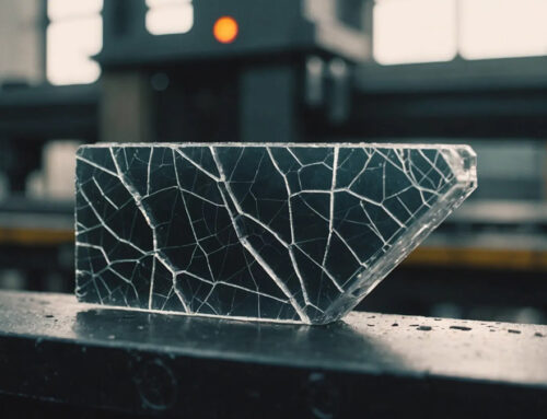
Flash and burrs are common defects in injection molding, characterized by excess material protruding from the edges or surfaces of molded parts. These imperfections typically occur at the parting line, ejector pin locations, or near inserts, resulting from molten plastic escaping the mold cavity during the injection process.
The presence of flash and burrs can compromise both the aesthetic appeal and functionality of plastic components. They may necessitate additional post-processing to remove the excess material, leading to increased production costs and time. Moreover, if left unaddressed, these defects can affect the dimensional accuracy and structural integrity of the final product, potentially causing assembly issues or mechanical failures.
Effectively identifying and mitigating the causes of flash and burrs is essential for maintaining high product quality and optimizing manufacturing efficiency in injection molding operations.
Flash and burrs are common defects encountered in injection molding. Though they might appear similar, they are distinct issues with specific causes and characteristics. Understanding these differences and the areas where they commonly occur can help in identifying and resolving the defects effectively.
1.1 Definitions and Distinctions Between Flash and Burrs
- Flash: This is the excess material that escapes from the mold cavity, typically at the parting line or other gaps in the mold. Flash is thin and flat, creating an unsightly finish on molded parts.
- Burrs: These are small, raised protrusions that appear at edges or features like gates and holes. Burrs are usually caused by irregularities in the mold or excessive injection pressure.

Flashes

Burrs
Though both defects are excess material, flash tends to be more widespread, while burrs are localized, smaller, and sharper.
1.2 Common Locations Where These Defects Occur in Molded Parts
- Parting Line: Flash commonly forms here when the mold halves are not properly aligned or when there’s insufficient clamping force.
- Ejector Pin Holes: Gaps created by the ejector pins during part removal can lead to flash or burr formation if the pins are misaligned or improperly fitted.
- Sliders or Cores: These moving parts in a mold can create gaps where flash or burrs can form, especially if the mold is misaligned.
- Vent Holes or Insert Features: Incorrect venting or poorly fitted inserts can allow excess material to leak, forming flash in these areas.
- Gates and Runners: Flash or burrs can form around the gates and runners due to flaws in the gate design or excessive injection pressure.
2. Impact on Product Quality and Performance
Flash and burrs are not just cosmetic issues—they can also significantly impact the functionality, safety, and overall performance of molded parts. Addressing these defects is crucial for maintaining high product quality, and here’s how they can affect your parts:
2.1 Aesthetic Concerns
- Visual Defects: Flash and burrs can create an unattractive appearance, leading to parts that look unprofessional or poorly made. For products with visible surfaces, such as consumer goods, this can affect brand reputation and customer perception.
- Surface Imperfections: The presence of flash or burrs on the surface of a part can make it difficult to achieve smooth finishes, which are often essential in applications requiring high aesthetics, such as automotive interiors or medical devices.

2.2 Functional Issues
- Impaired Fit and Assembly: Flash and burrs can interfere with the precise fit of components, preventing smooth assembly. This can lead to parts that don’t align correctly or don’t function as intended when integrated into larger assemblies.
- Inconsistent Tolerances: These defects can cause variations in part dimensions, affecting the overall functionality of the product. For instance, a burr on a part may prevent it from fitting into a mating component, leading to mechanical failure or reduced performance.
- Interference with Moving Parts: Burrs or flash in areas where moving parts interact can cause binding, increased friction, or wear over time, compromising the part’s longevity and operational efficiency.

2.3 Potential Safety Hazards
- Sharp Edges: Burrs, in particular, can create sharp edges or points on molded parts, which may pose safety risks during handling or in the final application of the product. This is especially critical for products like medical devices, toys, or automotive components where safety is paramount.
- Risk of Injury: Flash and burrs can cause injury to workers during assembly or use, leading to potential liability concerns. Furthermore, improperly deburred or flashed parts may lead to operational malfunctions, potentially resulting in accidents or equipment damage.

3. Common Causes of Flash and Burrs
Flash and burrs in injection molding are often the result of various factors that stem from mold design, material properties, and process parameters. A thorough understanding of these common causes can help pinpoint the underlying issues and facilitate effective solutions.
3.1 Mold-related Factors

3.1.1 Poor Mold Design or Wear Leading to Improper Sealing
- Design Flaws: Flash can occur when the mold is poorly designed, especially at the parting line, ejection system, or venting channels. If the mold does not have adequate clearance, or the parting lines are not precisely aligned, it allows molten material to escape into areas where it should not be, leading to flash and burrs.
- Mold Wear: Over time, the mold cavity can wear down, especially at high-stress points such as the parting line. As the mold wears, it may no longer seal tightly during injection, allowing molten plastic to leak out and create flash. Regular maintenance, mold repairs, and quality control during mold construction are necessary to minimize these risks.
3.1.2 Inadequate Clamping Force Allowing Material Leakage
- Clamping Force Imbalance: Clamping force is essential for holding the mold halves together during the injection process. If the clamping force is too low, it allows the mold to open slightly under the pressure of the injected material, causing leakage of plastic at the parting line. This can result in flash formation. Insufficient clamping force may also lead to mold distortion, especially with high-pressure injection, which exacerbates the problem.
- Misaligned or Worn Components: When clamping mechanisms or ejector pins are misaligned or worn out, it can cause uneven pressure distribution across the mold, leading to inconsistent molding conditions that promote flash or burr formation.
3.2 Material-related Factors

3.2.1 Low Viscosity Materials Prone to Escaping Mold Cavities
- Material Flow Characteristics: Materials with low viscosity, such as certain grades of polyethylene or polypropylene, flow more easily than higher viscosity materials. While this is beneficial for filling complex mold cavities, it can also cause problems if the material is too fluid. In cases of low viscosity, the material may flow into small gaps at the parting line or around ejection pins, creating flash.
- Excessive Material Flow: When a material’s viscosity is too low for the processing conditions, the melt tends to flow more easily out of the mold cavity during injection, often leading to unintended overflow. To avoid flash, it is crucial to select the right material for the application, considering its viscosity and the mold design requirements.
3.3 Process-related Factors

3.3.1 High Injection Pressure or Speed Causing Material Overflow
- Injection Pressure: Excessively high injection pressure forces more material into the mold cavity than necessary, especially if the clamping force is inadequate to counteract this pressure. This excess pressure can cause the material to squeeze out from the mold cavity at the parting line, resulting in flash.
- Injection Speed: High injection speeds can also contribute to flash, as the rapid movement of material may force it into unwanted areas. This is particularly true when the mold is not designed to handle such fast injection cycles or if it does not have adequate venting. Overly aggressive injection speeds can also lead to issues like warping, air entrapment, or flash.
- Optimizing Injection Speed and Pressure: Reducing the injection speed and pressure can help avoid unnecessary material overflow. Carefully balancing these factors is essential for achieving clean, accurate mold fills without the risk of flash formation.
3.3.2 Excessive Barrel or Mold Temperatures Reducing Material Viscosity
- High Barrel Temperature: If the temperature inside the injection molding machine barrel is set too high, it can reduce the material’s viscosity, making it more prone to flowing past the parting line. This can cause the material to escape the cavity and form flash at the parting line.
- Mold Temperature: Similarly, if the mold temperature is excessively high, the material will not solidify quickly enough after being injected into the cavity. This can lead to excess flow that extends beyond the cavity, forming flash or burrs. It can also affect the material’s crystallization process, leading to inconsistent cooling and further exacerbating defects.
- Control and Optimization: Maintaining the appropriate barrel and mold temperatures for the specific material being used is crucial. Ensuring that temperatures remain within the recommended range will help control viscosity and minimize the risk of flash.
By identifying and addressing these common causes of flash and burrs, manufacturers can reduce the frequency and severity of these defects. Careful attention to mold design, material selection, and process parameters will help ensure the production of high-quality molded parts, ultimately improving both the functionality and appearance of the final products.
4. Mold Design and Maintenance Solutions
Effective mold design and consistent maintenance are critical for preventing flash and burrs in injection molding. By ensuring precise alignment, reducing wear, and optimizing venting, manufacturers can minimize material leakage and improve part quality.
4.1 Ensuring Precise Mold Alignment and Fit
- Precision in Mold Construction:
Accurate mold design is essential to ensure proper alignment between the core and cavity. Misalignment or poor fit at the parting line creates gaps where molten material can escape, forming flash.- Tight Tolerances: During mold manufacturing, precise tolerances (typically within ±0.01 mm) must be maintained to prevent gaps that lead to flash.
- Consistent Parallelism: The mold plates and parting surfaces should be perfectly parallel to avoid uneven clamping force, which can cause flash on one side of the part.
- Optimizing Mold Closure:
When molds do not close properly, either due to misalignment or uneven force distribution, flash is likely to occur.- High-precision mold bases: Use accurately machined mold bases to prevent uneven closing gaps.
- Balanced clamping: Ensure that the clamping force is evenly distributed across the mold surface to prevent partial gaps.
- Accurate Component Fit:
Proper fitting between mold components, such as inserts, sliders, and cores, is vital to prevent material leakage.- Polishing and fitting: During mold assembly, precision fitting techniques like blue or red lead fitting are used to ensure complete contact without gaps.
- Reinforced guide pins and bushings: Installing robust guide pins and bushings ensures repeatable, accurate alignment and reduces the risk of misalignment over time.

4.2 Regular Inspection and Maintenance to Prevent Wear
- Routine Mold Inspection:
Regular inspection of molds is necessary to detect early signs of wear or misalignment that could lead to flash formation.- Check parting line and cavities: Inspect the parting line and cavity edges for wear, dents, or burrs, as they create pathways for material overflow.
- Examine mold surface finish: Worn or rough mold surfaces can create uneven contact, allowing material seepage. Periodic polishing can restore smoothness and sealing performance.
- Preventive Maintenance:
Routine maintenance extends mold lifespan and prevents issues that lead to flash or burrs.- Lubrication and cleaning: Regularly lubricate moving parts (e.g., sliders, ejector pins) to prevent sticking or uneven movement, which can create molding inconsistencies.
- Parting line repair: If wear or deformation is detected, the parting line should be repaired or re-machined to restore a tight seal.
- Addressing Mold Fatigue:
Molds used for high-volume production are prone to fatigue, resulting in deformation or subsidence.- Plate reinforcement: Add support plates or backing plates to high-stress areas to maintain dimensional stability.
- Mold rework: For severely worn molds, rework the mold cavity or replace worn components to restore precision.

4.3 Implementing Proper Venting to Avoid Gas Traps
- The Role of Venting:
Proper venting channels are necessary to allow trapped gases and air to escape during the injection process. Without adequate venting, internal pressure can force molten plastic into unintended gaps, forming flash or burrs. - Optimized Vent Placement:
Vents should be strategically placed at the ends of flow paths, near thin walls, or at areas prone to air entrapment.- Vent dimensions: Standard vent thickness ranges between 0.02 mm and 0.05 mm for most thermoplastics. Larger vents may lead to flash, while smaller ones may not release enough gas.
- Continuous vent cleaning: Vents should be cleaned regularly to prevent clogging, which can hinder gas escape and increase internal mold pressure.
- Using Vacuum Venting Systems:
For complex or large parts, vacuum venting systems can be implemented. These systems actively remove trapped air, preventing pressure buildup that could cause flash.- Improved mold fill balance: Vacuum venting ensures better cavity filling, reducing the risk of inconsistent flow and flash formation.
- Enhanced surface quality: Proper venting reduces gas traps, minimizing blemishes or surface defects caused by flash.
- Vent Depth and Width Optimization:
When flash occurs near the venting area, it may indicate that the vents are too large.- Refined vent sizing: Decrease the vent depth and width slightly to minimize material escape while still allowing gas to dissipate effectively.

By prioritizing precision in mold alignment, implementing regular maintenance, and optimizing venting systems, manufacturers can significantly reduce the occurrence of flash and burrs. These proactive measures not only improve part quality but also extend the longevity and reliability of the molds.
5. Material Selection and Handling Strategies
Proper material selection and handling play a critical role in preventing flash and burrs in injection molding. By using materials with suitable flow properties and maintaining their integrity during processing, manufacturers can minimize the likelihood of these defects.
5.1 Choosing Materials with Appropriate Flow Characteristics
- Impact of Material Flowability on Flash Formation:
The flow characteristics of plastic directly influence its tendency to leak into small mold gaps, leading to flash.- Low-viscosity materials (e.g., polyethylene, polypropylene) have higher flowability and are more prone to flash.
- High-viscosity materials (e.g., PVC, PEEK) have lower flowability, making them less likely to seep through mold seams.
- Material viscosity control: Selecting a material with medium viscosity offers a balance between filling efficiency and flash prevention.
- Material Selection Based on Application:
When choosing materials, manufacturers must consider the part design, wall thickness, and required mechanical properties.- For thin-walled parts: Use resins with moderate flowability (e.g., ABS, PC) to ensure proper mold filling without excessive leakage.
- For thick-walled parts: Opt for higher-viscosity resins to reduce the risk of flash due to slower flow.
- For high-precision parts: Use engineering-grade materials with stable flow characteristics (e.g., PBT, POM) to minimize flash.
- Material Additives to Adjust Flow:
In some cases, additives or modifiers can be introduced to adjust material flow behavior.- Flow enhancers: Increase melt fluidity, useful for filling intricate molds but may increase the risk of flash.
- Flow retarders: Reduce flowability, making the material less prone to flash but potentially increasing short shot risks.
- Use cautiously: Modifying additives should be tested carefully, as they can affect part strength and surface finish.
- Material Compatibility with Mold Design:
Ensure the selected plastic is compatible with the mold design and processing conditions.- Material-specific venting: Low-viscosity materials require tighter vent clearances (0.02–0.03 mm), while high-viscosity materials need larger vents (0.05–0.08 mm) to avoid gas traps.
- Shrinkage compensation: Account for material shrinkage rates to prevent post-molding flash due to part warping or dimensional changes.
5.2 Proper Drying and Handling to Maintain Material Integrity
- Importance of Proper Drying:
Moisture contamination in plastic resins can lead to inconsistent melt viscosity, increasing the risk of flash.- Hygroscopic materials (e.g., nylon, ABS, PET) absorb moisture from the air, which reduces their viscosity during molding, making them prone to flash.
- Drying standards: Follow recommended drying temperatures and times to maintain material consistency. Below is a table of Drying Standards for Common Injection Molding Materials for your reference.
| Material | Drying Temperature (°C) | Drying Time (hours) | Special Considerations |
| ABS | 80–90°C | 2–4 | Prevents surface defects and flash formation. |
| Nylon (PA) | 75–90°C | 4–6 | Requires thorough drying due to high moisture absorption. |
| Polycarbonate (PC) | 110–130°C | 3–5 | Improper drying can cause bubbles and flash. |
| PET | 120–160°C | 4–6 | Critical to avoid hydrolysis during molding. |
| PBT | 100–120°C | 2–4 | Moisture significantly reduces strength. |
| PPS | 130–150°C | 2–3 | Requires low moisture content for precision parts. |
| PMMA | 75–85°C | 2–4 | Ensures optical clarity and prevents surface defects. |
| PEEK | 150–160°C | 2–3 | Essential for maintaining high-performance properties. |
| TPU | 80–100°C | 2–3 | Moisture causes degradation and flash issues. |
| Polyethylene (PE) | No drying required | N/A | Low moisture absorption; drying is unnecessary. |
| Polypropylene (PP) | No drying required | N/A | Generally does not require pre-drying. |
Tip: For highly hygroscopic materials (e.g., Nylon, PET, PBT), use dehumidifying dryers instead of hot-air dryers to prevent moisture-related defects, such as flash, bubbles, and surface blemishes.
-
- Dehumidifying dryers: Use dehumidifying dryers instead of hot-air dryers for highly hygroscopic materials to prevent moisture-related defects.
- Material Handling Best Practices:
Proper handling techniques prevent contamination or material degradation, reducing the risk of flash formation.- Sealed storage: Store raw materials in airtight containers or vacuum-sealed bags to prevent moisture absorption.
- Temperature-controlled storage: For heat-sensitive materials, maintain consistent storage temperatures to avoid premature degradation.
- Clean handling: Ensure handling equipment (e.g., hoppers, loaders) is clean and free of debris to prevent contamination, which can affect material consistency and increase flash risk.
- Consistent Material Feeding:
Inconsistent feeding rates or uneven granule sizes can cause variations in the melt flow, leading to flash formation.- Use consistent batch sizes: Ensure material batches are uniform to prevent variations in flow properties.
- Proper feeder calibration: Regularly calibrate and test feeders to maintain steady and accurate material flow rates.
- Material Testing and Quality Control:
Conduct regular quality checks on incoming raw materials to verify their consistency and flow properties.- Melt Flow Index (MFI) testing: Verify the material’s viscosity using MFI tests to ensure it meets processing specifications.
- Batch-to-batch consistency: Ensure that material properties remain consistent across production batches to avoid sudden flash issues caused by material variability.
6. Optimizing Injection Molding Process Parameters
Fine-tuning injection molding process parameters is essential for preventing flash and burrs. By controlling pressure, speed, temperature, and holding time, manufacturers can reduce the likelihood of material overflow while maintaining part quality and dimensional accuracy.
6.1 Adjusting Injection Pressure and Speed to Appropriate Levels
- Impact of Excessive Pressure and Speed on Flash Formation:
High injection pressure and speed increase the force exerted on the mold, potentially causing it to separate slightly at the parting line. This separation creates gaps, allowing molten material to seep through, resulting in flash.- Excessive pressure: Forces the material to overflow, especially around thin-walled areas or cavity edges.
- High injection speed: Increases shear stress, making the plastic more fluid and prone to leakage through mold gaps.
- Inconsistent pressure: Leads to uneven cavity filling, increasing the risk of flash in specific areas.
- Optimal Pressure and Speed Settings:
Adjusting injection pressure and speed to the correct levels is crucial for achieving proper cavity filling without overpacking or causing flash.- Initial fill speed: Use a moderate injection speed to prevent turbulence and minimize flash formation.
- Gradual acceleration: Gradually increase speed once the flow stabilizes to ensure smooth and complete cavity filling.
- Pressure reduction: Reduce holding pressure after the cavity is filled to prevent material from squeezing through parting lines.
- Recommended settings:
- Low-viscosity materials (e.g., PP, PE): Use lower injection pressures to prevent material from escaping mold cavities.
- High-viscosity materials (e.g., PVC, PEEK): Use higher pressures but maintain moderate speed to avoid flash.
- Thin-walled parts: Reduce speed and pressure to minimize mold separation.
- Thick-walled parts: Use higher pressures and speeds to ensure complete filling without premature cooling.
- Pressure and Speed Ramp Control:
Gradually ramping up or down the pressure and speed helps prevent sudden force spikes that can lead to flash.- Profiled injection: Use multi-stage injection profiles, starting with a lower speed and gradually increasing it to fill the cavity smoothly.
- Deceleration phase: Reduce speed near the end of the filling phase to prevent excessive force buildup.
6.2 Setting Optimal Barrel and Mold Temperature
- Effect of Temperature on Material Flow:
Barrel and mold temperatures directly impact the viscosity and flow behavior of the plastic.- High barrel temperature:
- Lowers material viscosity, making it more fluid and prone to flash.
- Can cause overfilling or overflow due to reduced resistance.
- Low barrel temperature:
- Increases material viscosity, reducing its flowability.
- May result in incomplete filling or short shots rather than flash.
- High mold temperature:
- Slows down material cooling, keeping it in a fluid state longer.
- Increases the chance of material seeping into mold gaps, causing flash.
- Low mold temperature:
- Accelerates cooling, reducing material flow and minimizing the risk of flash.
- Can lead to premature cooling defects like flow marks or weld lines.
- High barrel temperature:
- Recommended Temperature Settings:
Setting optimal barrel and mold temperatures based on material properties reduces the risk of flash. Below is a table of Recommended Temperature Settings for Common Injection Molding Plastics for your convenience.
| Plastic Type | Example Materials | Barrel Temperature (°C) | Mold Temperature (°C) | Key Considerations |
| Semi-Crystalline | POM, PA, PBT, PE, PP | 210–250 | 80–110 | Moderate temperatures for controlled flowability. |
| Amorphous | ABS, PC, PMMA, PS | 230–280 | 60–90 | Higher mold temperatures reduce internal stresses. |
| Heat-Sensitive | PVC, EVA, TPU | 160–190 | 30–50 | Precise control prevents degradation and flashing. |
| High-Temperature Resistant | PEEK, PPS, LCP | 340–400 | 150–200 | Requires high processing temperatures. |
| Soft Thermoplastics | TPE, TPR, LDPE | 170–210 | 30–60 | Lower temperatures prevent flashing and warping. |
- Temperature Uniformity:
Maintaining consistent temperature distribution across the mold is essential for preventing flash.- Hot runner systems: Ensure even temperature distribution in hot runners to prevent material flow imbalances.
- Cooling channels: Regularly clean cooling channels to maintain uniform mold temperature.
- Thermocouples and heaters: Calibrate and inspect temperature control systems to prevent overheating or uneven heating.
6.3 Controlling Holding Time and Pressure to Prevent Overpacking
- Influence of Holding Time and Pressure on Flash Formation:
Holding time and pressure directly impact how much material is packed into the cavity during the cooling phase.- Excessive holding pressure:
- Causes overpacking, forcing material into mold gaps, creating flash.
- Increases residual stress in the part, potentially causing warping.
- Prolonged holding time:
- Keeps the material under pressure for longer, increasing the chance of material seeping through mold gaps.
- May cause part deformation or dimensional inconsistencies.
- Insufficient holding pressure:
- Results in incomplete cavity filling.
- Can lead to sink marks and dimensional inaccuracies.
- Excessive holding pressure:
- Optimizing Holding Parameters:
Properly controlling holding pressure and time helps prevent flash while ensuring part integrity.- Gradual pressure reduction:
- Use a two-stage holding phase: start with moderate holding pressure, then gradually reduce it to prevent overpacking.
- Holding time calibration:
- Adjust holding time based on part thickness and material shrinkage characteristics.
- For thin-walled parts, reduce holding time to avoid material seepage.
- For thick-walled parts, increase holding time moderately to ensure proper packing without flash.
- Pressure consistency:
- Use consistent holding pressure throughout the molding cycle to prevent flash due to pressure variations.
- Gradual pressure reduction:
- Recommended Holding Time and Pressure Guidelines:
- Thin-walled parts: 1–3 seconds of holding time with moderate pressure.
- Thick-walled parts: 5–10 seconds of holding time with slightly higher pressure.
- High-viscosity materials: Lower holding pressure to reduce flash risk.
- Low-viscosity materials: Use slightly higher holding pressure but reduce holding time to prevent flash.
7. Case Studies
Examining real-world examples of flash and burr issues in injection molding provides valuable insights into the common causes and effective solutions. By analyzing specific cases, manufacturers can better understand how to diagnose and resolve these defects in their own production processes.
7.1 Real-World Examples of Flash and Burr Issues
- Case 1: Flash Formation in Router Housing Production

-
- Material Used: Polycarbonate (PC)
- Problem:
The manufacturer initially used PC to mold router housings without flash issues. However, after switching to Polybutylene Terephthalate (PBT) for cost-efficiency, noticeable flash appeared around the parting line and ejector pin areas. - Cause:
The mold was originally designed with a 0.06 mm overflow tolerance, suitable for PC’s higher viscosity. However, PBT’s lower viscosity and greater flowability allowed it to seep into small mold gaps, generating flash. - Solution:
- Mold modification:
- The mold parting line tolerance was reduced to 0.02 mm to match PBT’s lower viscosity.
- Ejector pin clearance was tightened to prevent seepage.
- Process adjustments:
- Injection speed was reduced to prevent excessive force on the mold.
- Clamp force was increased to prevent parting line separation.
- Outcome:
- Flash formation was eliminated, and the production efficiency improved with fewer rejected parts.
- Mold modification:
- Case 2: Flash on Automotive Connector Housings

-
- Material Used: Polyamide (PA66) with glass fiber
- Problem:
An automotive parts manufacturer faced recurring flash on connector housings, particularly around the slider inserts and venting areas. The flash reduced the precision of the connectors, leading to poor assembly fit. - Cause:
- Poor mold alignment:
- The mold exhibited slight misalignment due to uneven thermal expansion, creating small gaps around the sliders.
- Inadequate venting:
- Trapped air in the mold cavity increased back pressure, pushing the molten material into unintended gaps.
- High injection pressure:
- Excessive pressure caused material overflow, exacerbating the flash issue.
- Poor mold alignment:
- Solution:
- Mold rework and maintenance:
- The mold alignment was corrected by regrinding the slider surfaces and adding guiding pins.
- Venting channels were cleaned and widened to prevent gas buildup.
- Process optimization:
- The injection pressure was reduced by 15% to prevent excessive force.
- The injection speed was optimized to prevent rapid cavity filling.
- Outcome:
- The flash issue was eliminated, resulting in better dimensional consistency and improved connector fit.
- The rejection rate dropped by 22%, increasing production efficiency.
- Mold rework and maintenance:
- Case 3: Burr Formation in Consumer Electronics Casings

-
- Material Used: Acrylonitrile Butadiene Styrene (ABS)
- Problem:
During the production of consumer electronics casings, burrs repeatedly formed along the ejector pin locations and parting lines. This not only compromised the aesthetic quality but also made the parts unsafe for end-users due to sharp edges. - Cause:
- Excessive holding pressure:
- The manufacturer applied high holding pressure to achieve better cavity filling, but this led to material leakage around the parting lines.
- Improper mold clamping:
- The clamping force was insufficient, allowing slight separation between mold halves, creating small gaps for the material to escape.
- Worn mold edges:
- The mold parting line surfaces had minor wear, making it difficult to maintain a tight seal.
- Excessive holding pressure:
- Solution:
- Process optimization:
- The holding pressure was reduced by 20%, preventing overpacking and reducing material leakage.
- The mold clamping force was increased to prevent separation at the parting line.
- Mold maintenance:
- The parting line surfaces were polished to restore sealing precision.
- Outcome:
- The burrs were successfully eliminated, and the cosmetic quality of the casings improved.
- Production consistency increased, reducing defect rates by 30%.
- Process optimization:
7.2 Analysis of Causes and Implemented Solutions
These case studies highlight several recurring causes of flash and burr formation in injection molding and the solutions manufacturers implemented to resolve them:
- Common Causes Identified:
- Material-related factors:
- Lower-viscosity materials (e.g., PBT, PA66) tend to seep into small mold gaps, creating flash.
- Improper material handling, such as insufficient drying, increases the likelihood of defects.
- Mold-related factors:
- Poor alignment and worn parting lines result in material leakage.
- Inadequate venting causes gas buildup, increasing back pressure and forcing material into unintended gaps.
- Process-related factors:
- High injection pressure and holding force lead to overpacking and flash.
- Insufficient clamping force allows mold separation, contributing to flash formation.
- Material-related factors:
- Effective Solutions Applied:
- Mold modification and maintenance:
- Tightening mold tolerances and maintaining parting line integrity effectively reduces flash risks.
- Enhancing venting efficiency prevents gas traps that contribute to flash formation.
- Process optimization:
- Reducing injection pressure and holding time minimizes material overflow.
- Fine-tuning clamping force ensures mold stability during injection.
- Material selection and handling:
- Switching to higher-viscosity materials or adjusting process parameters to suit the material properties prevents flash.
- Proper material drying and handling improves consistency and reduces defects.
- Mold modification and maintenance:
These case studies demonstrate that preventing and resolving flash and burrs in injection molding requires a combination of mold precision, process optimization, and material control. By applying these solutions, manufacturers can enhance product quality, reduce defects, and improve overall production efficiency.
8. Preventive Measures and Best Practices
To effectively minimize the occurrence of flash and burrs in injection molding, manufacturers need to implement robust preventive measures and follow best practices. By proactively addressing mold design, process monitoring, and workforce training, companies can enhance product quality and reduce defect rates.
8.1 Comprehensive Mold Design Review
A thorough mold design review is essential for preventing flash and burrs before production begins. Identifying and correcting potential issues in the mold design stage significantly reduces the likelihood of defects.
- Precision parting line fit:
- Ensure that parting lines are precisely machined and properly aligned to prevent material leakage.
- Use tighter tolerances on mold parting surfaces, especially for low-viscosity materials.
- Apply interlocking features (e.g., tongue-and-groove or stepped parting surfaces) to improve sealing integrity.
- Proper venting and gas relief:
- Design adequate venting channels to prevent gas traps, which can increase back pressure and force material into unintended areas.
- Regularly clean and inspect venting channels to maintain efficiency.
- For high-viscosity materials, ensure vents are large enough to release trapped air without allowing material seepage.
- Uniform cavity filling:
- Use a balanced runner system to ensure even filling across all cavities.
- Optimize gate locations and sizes to prevent uneven material distribution, which can lead to flashing.
- Minimize the number of cavities for precision parts to reduce the risk of dimensional inconsistencies.
- Robust mold construction:
- Ensure molds are made from durable, wear-resistant materials (e.g., hardened tool steel) to prevent deformation over time.
- Design molds with reinforced plates and support structures to maintain stability under clamping force.
8.2 Regular Process Monitoring and Parameter Adjustments
Continuous monitoring of the injection molding process and real-time parameter adjustments are critical for preventing flash and burr formation. Consistent process control ensures stable production and minimizes the occurrence of defects.
- Clamping force monitoring:
- Regularly verify and calibrate the clamping force to prevent mold separation during injection.
- Use pressure sensors to detect and correct inconsistencies in clamping force.
- Ensure the clamping force is sufficient to counteract the injection pressure, preventing mold gaps.
- Injection speed and pressure control:
- Use controlled injection speeds to prevent excessive shear forces that can force material into mold gaps.
- Adjust injection pressure to match material viscosity and cavity dimensions.
- Gradually ramp up injection speed rather than applying it suddenly to reduce the risk of flash.
- Temperature regulation:
- Maintain consistent barrel and mold temperatures within the optimal range for the material used.
- Avoid overheating, which can reduce material viscosity and increase the risk of flashing.
- Implement temperature control systems to ensure stability, especially for multi-cavity molds.
- Automated process monitoring:
- Use real-time monitoring systems to track key process parameters (e.g., temperature, pressure, clamping force).
- Set automatic alarms for deviations to prevent prolonged production with faulty settings.
- Utilize statistical process control (SPC) to identify trends and make timely adjustments.
8.3 Continuous Training for Personnel on Defect Prevention
Well-trained staff plays a crucial role in identifying and preventing flash and burr issues. Continuous education ensures operators and technicians stay current with best practices and emerging technologies.
- Defect identification and troubleshooting:
- Train personnel to recognize early signs of flash and burr formation, such as surface irregularities or slight material seepage.
- Teach effective troubleshooting techniques to quickly address root causes, such as adjusting clamping force or reducing injection pressure.
- Process optimization skills:
- Equip staff with knowledge of process optimization strategies to prevent overpacking and material leakage.
- Provide practical training on adjusting injection parameters (pressure, speed, temperature) for different materials.
- Conduct regular workshops on mold maintenance and vent cleaning to prevent recurring flash issues.
- Use of advanced monitoring tools:
- Train operators to interpret data from real-time monitoring systems for proactive defect prevention.
- Teach proper calibration and adjustment techniques to maintain optimal process conditions.
- Standardized protocols:
- Develop and implement standard operating procedures (SOPs) for defect prevention.
- Include step-by-step guidelines for parameter adjustments, mold inspections, and defect analysis.
- Regularly update SOPs to reflect the latest process improvements and best practices.
8.4 Key Takeaway:
By integrating comprehensive mold design reviews, regular process monitoring, and ongoing personnel training, injection molding manufacturers can significantly reduce the occurrence of flash and burrs. These preventive measures not only enhance product quality and reduce waste but also improve operational efficiency and customer satisfaction.
Conclusion
Effectively eliminating flash and burrs in injection molding requires a holistic approach that integrates precise mold design, appropriate material selection, and data-driven process optimization. With advancing technology, manufacturers can further enhance defect prevention through computer-aided engineering (CAE) and artificial intelligence (AI) solutions.
Future Trends: AI/ML Integration for Predictive Defect Control
The future of injection molding lies in AI- and machine learning (ML)-powered defect prevention. As the industry moves toward Industry 4.0, the following advancements will drive further improvements in flash and burr control:
- Predictive defect detection:
- AI algorithms will analyze historical production data to predict conditions prone to flash or burrs.
- Real-time anomaly detection systems will automatically adjust parameters to prevent defects before they occur.
- Automated process optimization:
- AI-driven process control will dynamically fine-tune injection speed, pressure, and temperature based on live production data.
- Adaptive learning models will continuously improve accuracy by refining the process over time.
- Smart mold monitoring systems:
- Integrated IoT sensors will track mold alignment, wear, and venting efficiency, ensuring consistent mold performance.
- AI-based maintenance scheduling will proactively recommend repairs or replacements, preventing defect-prone conditions.
- CAE + AI synergy:
- Combining CAE mold flow simulations with AI-powered defect prediction will streamline mold design iterations.
- This will reduce design errors, minimize the need for physical prototypes, and optimize defect-free production conditions.
By embracing data-driven strategies and emerging AI technologies, manufacturers can achieve superior defect control, enhanced product quality, and higher production efficiency. As predictive defect management becomes the norm, companies that leverage these innovations will gain a significant competitive edge in the injection molding industry. At KingStar Mold, we combine cutting-edge technology with expert craftsmanship to deliver precision-molded parts with minimal defects, helping our clients achieve consistent quality and cost efficiency.
Want to get free quote for your injection molding project? Need technical support? Write to sales@kingstarmold.com or leave online message, you will receive our detailed reply within 24 hours.