Nowadays, many products are trending towards being “light, small, and thin,” such as mobile phones, headphones, and even disposable food containers. Thin-wall injection molding is the key technology supporting this trend. Today, we’ll start with the most basic concepts and clearly explain the core aspects of this technology, so that both beginners who are new to it and professionals looking to fill in knowledge gaps can understand.
As a leading plastic injection molding company, we have rich experience in thin wall injection molding. We work this post out for our clients and small and medium-sized injection molding factories.
1. What Exactly is “Thin-Walled”?
Many people think “thin-walled” means a thickness of less than 1mm. This isn’t entirely wrong, but it’s not comprehensive enough. To determine whether something is thin-walled, three dimensions need to be considered:
1)First, a simple standard: if the plastic part’s wall thickness is indeed less than 1mm, it can basically be classified as thin-walled.
2)The more crucial factor is the ‘flow path/wall thickness ratio’ (we’ll abbreviate it as L/t). Here, ‘flow path L’ refers to the distance from the mold’s main runner to the farthest point of the plastic part; ‘wall thickness t’ is the thickness of the plastic part itself. When this ratio exceeds 150, it is considered thin-walled. If the wall thickness of the plastic part varies in different areas, you need to calculate the L/t for each segment separately and then sum them up.
3)Additionally, we need to consider the properties of the plastic itself: one is the viscosity factor, for example, the viscosity factor for PP plastic is 1, and for PC it is 2, so when calculating, L/t should be multiplied by this number; the other is the heat transfer coefficient. For instance, some casings may add metal powder to improve thermal conductivity, and in such cases, the heat transfer factor must also be taken into account.
Two practical examples make it clearer: a disposable PP food container, with a flow length of 135mm and a wall thickness of 0.45mm, has an L/t of 300; a PC casing for a mobile phone battery, with a flow length of 38mm and a wall thickness of 0.25mm, has an L/t of 152. Multiply by the viscosity factor of 2 for PC, and it becomes 304, which is similar to the food container situation, both of which are considered thin-walled.

2. Why Insist on Making Thin-Walled Injection Molding?
First, it can save costs. The plastic used to make plastic components often accounts for 50%-80% of the total cost of the finished product. Thin-wall designs can directly reduce the amount of plastic used, naturally lowering costs. For products produced in large quantities, these savings are quite significant.
Second, it follows product trends. Current consumer electronics, such as mobile phones, MP3 players, and digital cameras, all pursue compact and lightweight designs. If the plastic components inside the device are too thick, they simply cannot meet these design requirements, making thin-wall designs the inevitable choice.
3. The Essence of “Thin-Walled Filling”
The key stage in thin-wall injection molding is ‘filling’—injecting molten plastic into the mold cavity. However, the mold walls are cold, and as soon as the plastic touches the mold wall, a layer of solidified plastic forms. This solidified layer narrows the channel through which the plastic can flow.
The thinner the wall, the more severe this problem becomes. For example, for a 1mm-thick plastic part, a 0.2mm solidified layer forms, leaving an actual flow channel of only 0.6mm. If the wall is only 0.5mm thick, the solidified layer is still 0.2mm, leaving a flow channel of just 0.1mm. If the plastic hasn’t fully filled the mold cavity, the flow channel gets blocked by the solidified layer, resulting in a plastic part with missing sections, ultimately becoming scrap.

4. Several Core Technologies Must Be Mastered in Thin-Wall Injection Molding
4.1 Achieve “Speed”: High-Speed Filling is Key
Since the solidified layer can block the channels, the mold cavity must be filled before the solidified layer thickens—this requires “high-speed injection.” Ordinary injection molding machines, which operate at 100 mm per second, are simply not fast enough, so ways to increase speed must be found:
- Using a larger oil pump can increase speed by 25%; using two pumps simultaneously can increase speed by 70%;
- ‘Regenerative injection’can more than double the speed, suitable for situations where high pressure is not needed at the beginning of injection;
- The most commonly used and effective method is the ‘nitrogen bottle (accumulator)’: high-pressure nitrogen is stored in a rubber bladder, surrounded by high-pressure oil, which, when injected, releases the oil all at once, providing a large instantaneous flow.
Currently, the injection speed is roughly divided into four levels: low speed (200-300mm/s), medium speed (300-600mm/s), high speed (600-1000mm/s), and ultra-high speed (1000-2000mm/s). Our domestically-made injection molding machines can basically reach medium speed.

4.2 Achieving “Stability”: Low-Inertia Design is Essential
Fast speed alone is not enough; it also needs to ‘start and stop quickly’. For example, if the total injection time is only 0.5 seconds, it’s best to reach the full speed of 400 mm/s within 0.05 seconds, which requires an acceleration of over 8G (faster than a roller coaster). If the acceleration is too slow, say it takes 0.3 seconds to reach full speed, the average speed will drop and the mold cavity still won’t fill properly.
To achieve such rapid acceleration, the key is ‘reducing the weight of moving parts’. Many injection molding machines today use a dual-injection cylinder design, where even the rear seat and hydraulic motor move during injection, resulting in high weight and high inertia. In contrast, a single-injection cylinder design only moves the screw and piston during injection, which is much lighter, has lower inertia, and makes rapid acceleration easier to achieve.
4.3 Achieving “Precision”: High Rigidity + Accurate Control Are Both Essential
1)The oil circuit must be rigid. Hydraulic pressure has elasticity, so if the oil circuit is not sufficiently “hard,” the oil will compress during fast injection, affecting speed and accuracy. Therefore, it’s necessary to use large-sized cylinder pistons and short-stroke designs. The oil pipes should also be as short as possible, and hard pipes should be used instead of hoses whenever possible to reduce the impact of oil elasticity.
2)Use the right valve. Servo valves respond much faster than ordinary proportional valves. Especially after the plastic has filled the mold cavity, it’s crucial to switch immediately from “injection” to “holding pressure” (to prevent plastic backflow). A servo valve can precisely control this timing—switching too late causes flash on the part, while switching too early results in short shots.
3)Full closed-loop control. used with servo valves, it can monitor parameters such as injection speed and holding pressure in real time. Once there is a deviation from the set value, it adjusts immediately, resulting in plastic parts with good consistency and low scrap rates.
4)The controller must be sensitive. the controller (essentially the ‘brain’ of the injection molding machine) must be able to accurately capture the moment the mold cavity is filled. For example, if the injection speed is 400 mm/s with an allowable error of only 0.1 mm, the controller’s response time cannot exceed 0.25 ms. Either it scans the sensors every 0.1 ms, or it uses ‘real-time interrupt’ technology to immediately switch operations once the set position is reached.
4.4 Shorten the Injection Molding Cycle
Every second counts during mass production. There’s a simple method: ‘eject while opening the mold’ — as soon as the mold starts to open, push out the finished plastic part. This can save about 1 second per cycle.
To achieve this, the mechanical structure must keep up: the machine frame needs to be rigid enough, the mold plates should be thickened (for example, when the plastic part wall is 0.5mm thick, mold deformation should be controlled within 0.05mm), and a proportional valve should be used to control mold opening and closing to allow timely braking, preventing vibration during high-speed mold movements that could affect the quality of the plastic parts.
4.5 Enhancing Plastification Capability
When the injection molding cycle is shortened, the melting of the plastic (also known as “plastification”) must keep up. For example, with a 4-second cycle, the plastic must be melted properly within such a short time:
1)The screw can be designed with a twin-thread or extended screw (length-to-diameter ratio of 24-25) to increase the contact area between the plastic and the screw, allowing faster melting;
2)The screw rotation speed can be raised slightly; a surface speed over 1 m/s is fine and has no negative impact on commonly used plastics like PP;
3)A “pneumatic nozzle shut-off” can also be installed: when opening and closing the mold, the nozzle can hold the material while the screw continues to melt the plastic, essentially “parallel operation,” but two oil pumps are required.
5. Choosing the Right Molds and Plastics
5.1 Molds: Rigidity, Venting, and Precision Must Meet Standards
Molds serve as the “template” for plastic parts, and thin-walled injection molding has higher requirements for molds:
- Sufficient rigidity: The mold plates need to be thickened; otherwise, they will deform under injection pressure, leading to inaccurate wall thickness in the produced plastic parts;
- Smooth venting:During high-speed injection can trap the air in the cavity. If not vented properly, it will leave bubbles or short shots on the plastic part. Therefore, sufficient venting channels must be provided, vented mold steel can be used, or even vacuum can be applied;
- High precision:Especially for multi-cavity molds (making multiple plastic parts in one cycle), each cavity must have the same size and wall thickness, otherwise some parts will be qualified while others are defective;
- Quick demolding:Ejection mechanisms and air blast systems should be installed, so the part is ejected immediately after forming, and blown away by air. This allows the mold to close immediately for the next cycle, shortening the cycle time.
5.2 Prioritize Plastics With Good Fluidity
The fluidity of plastic directly affects the filling performance. For thin-wall injection molding, you must choose plastics with good fluidity:
1)For example, in PP plastics, the higher the melt index (MI), the better the fluidity. Some PP materials can reach an MI of 60g/10min (such as Basell’s Moplen RP1086), making them very suitable for thin-wall molding.
2)If you need both toughness and fluidity, PS/ABS alloys can be chosen—they combine the toughness of PC plastics with the good fluidity of ABS. Many electronic device casings use this material.
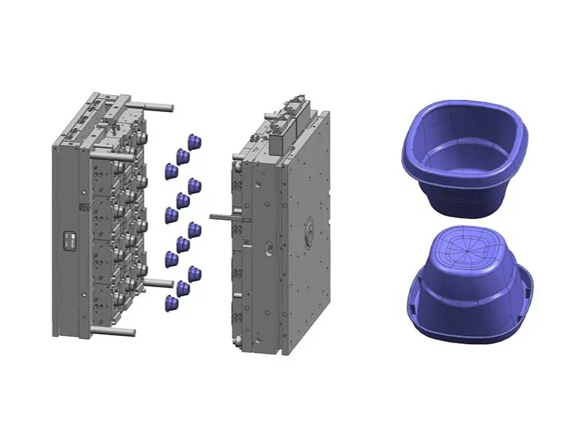
In fact, thin-wall injection molding cannot be achieved by relying on a single technology alone; it requires a systematic coordination of equipment, molds, plastics, and processes. The equipment must have high-speed and precise control capabilities, the molds must be rigid, precise, and well-vented, the plastic must have good fluidity, and the process parameters must be properly adjusted. Only when all these aspects are well-matched can you produce thin and high-quality plastic parts that meet product lightweight requirements while controlling costs. Whether making electronic components or packaging products, mastering these key points basically allows you to handle most of the challenges in thin-wall injection molding.
If you have any more questions or need us to make professional suggestions for your specific project, you’re welcomed to contact us by email (sales@kingstarmold.com) or fill out a from on our contact page. KingStar is a top custom manufacturing company in China. We have rich experience in one-stop on demand manufacturing.
