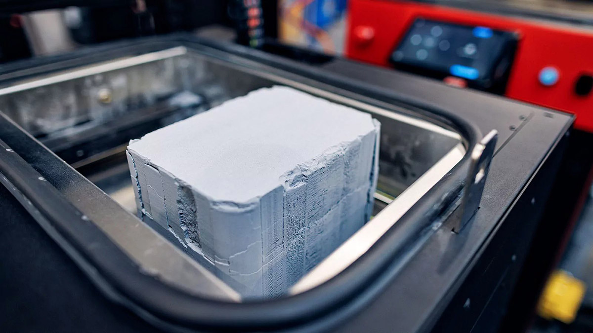
Selective Laser Sintering (SLS) is a powerful additive manufacturing technology that uses a laser to selectively sinter powdered material, fusing it into a solid structure. This process is ideal for creating complex, functional parts directly from 3D models, without the need for molds or tooling. Unlike other 3D printing methods, SLS produces strong and durable parts suitable for end-use applications.

- Additive Manufacturing Process: SLS works by heating and fusing powder particles layer by layer using a laser. The material fuses together in the desired shape, while the unsintered powder supports the part during the build process.
- Materials: SLS can work with a variety of materials, including nylons, TPU, and metal alloys, making it versatile for different industries and applications.
- Post-Processing: After printing, parts require cleaning to remove any remaining powder, which can be done manually or using automated systems.
Why SLS is Ideal for Functional Parts
- Durability and Strength: SLS parts are known for their high mechanical strength and isotropic properties, meaning they perform equally well in all directions. This makes them suitable for functional components that need to withstand stress and load.
- Complex Geometries: The technology allows for the creation of intricate and complex shapes that would be impossible or cost-prohibitive with traditional manufacturing methods like injection molding.
- No Need for Support Structures: Unlike other 3D printing technologies, SLS doesn’t require support structures since the surrounding powder acts as support. This increases design freedom and reduces post-processing time.
- Rapid Prototyping and Low-Volume Production: SLS is ideal for producing functional prototypes and low-volume production parts without the lengthy lead time and cost associated with injection molding.
Key Benefits of SLS for Design
Selective Laser Sintering (SLS) provides numerous advantages that enhance the design and manufacturing process. The technology is specifically tailored to support innovative and complex designs that are not achievable through traditional manufacturing methods.
Greater Design Freedom
- Flexibility in Design: SLS allows designers to create highly intricate parts without constraints. The lack of molds or tooling requirements means that the design process can be more creative and experimental.
- Material Versatility: A wide range of materials can be used in SLS printing, each suited for different applications. This flexibility enables designers to choose the material best suited for performance, cost, and aesthetic goals.
- Customization: SLS is ideal for customized parts, as changes can be easily incorporated into the design, allowing for rapid iteration and prototyping.
No Need for Support Structures
- Efficient Printing: Unlike FDM or SLA, SLS does not require external support structures during printing. The unsintered powder acts as a natural support, which reduces material waste and printing time.
- Post-Processing Advantages: With no support structures to remove, post-processing is simplified. The absence of support also allows for smoother surfaces on the final parts, reducing the need for additional finishing work.
Suitable for Complex Geometries
- Intricate Shapes: SLS excels at producing parts with intricate internal features, overhangs, and hollow sections. These designs are difficult or impossible to achieve with traditional methods like injection molding.
- Part Consolidation: Engineers can combine multiple parts into a single, consolidated component, eliminating the need for assembly. This reduces manufacturing time and costs, as well as improving the part’s strength and functionality.
- Design Complexity: SLS allows for geometries that integrate functionality, such as interlocking components or channels, without compromising part integrity or requiring additional steps.
Material Options for SLS 3D Printing
| Material | Characteristics |
| PA12 | Comparable to injection-molded polyamide, high dimensional stability, wear resistance, chemical resistance, and excellent mechanical properties. |
| Polyether block amide (PEBA) | Rubber-like thermoplastic polyamide elastomer, strong and flexible with high elongation at break, suitable for soft-touch parts. |
| Alumide | Aluminum-filled polyamide, combines high stiffness with good post-processing capabilities. Suitable for functional parts and high-performance applications. |
| Carbon-filled polyamide | High stiffness and strength, excellent for lightweight, high-strength parts. The carbon fiber enhances mechanical properties, reducing part warping. |
| Glass-filled polyamide | High stiffness and wear resistance, ideal for parts exposed to wear or high stress. Glass fibers improve dimensional stability. |
| PA11 | Environmentally friendly, high-impact resistance, and elongation at break, excellent for durable, flexible, and impact-resistant parts. |
| PEEK | Excellent mechanical properties, high-temperature resistance (up to 250°C), and potential for biocompatibility and sterilizability. Ideal for aerospace, automotive, medical parts. |
| TPU (Thermoplastic Polyurethane) | Flexible, strong, and durable material with high wear resistance. Suitable for soft, rubber-like parts, and flexible prototypes. |
| TPE (Thermoplastic Elastomer) | Offers high elasticity and flexibility, similar to rubber, but can be processed like plastic. Ideal for seals, gaskets, and flexible components. |
| HIPS (High Impact Polystyrene) | Easy to post-process, good impact resistance, used for producing tough, detailed parts. Often used for creating prototypes in low-volume production. |
| Stainless Steel 17-4 PH | Metal material offering high strength, corrosion resistance, and good thermal properties. Ideal for high-performance and functional parts in engineering applications. |
Optimizing Wall Thickness for SLS Parts

Recommended Wall Thickness Range
In Selective Laser Sintering (SLS), wall thickness plays a critical role in part quality and functionality. A typical recommended range is 0.7mm to 2mm for most parts, with 1mm being the ideal thickness. This ensures the part is both structurally sound and cost-effective. Parts with walls thinner than 0.7mm may suffer from insufficient strength or instability, while walls thicker than 2mm could increase material consumption and lead to longer print times.
Impact of Wall Thickness on Strength and Quality
The wall thickness of an SLS part directly impacts its mechanical strength, surface finish, and material efficiency. Understanding this relationship is key to designing optimized, functional parts.
- Thin Walls: While thinner walls reduce material usage and cost, they can compromise the strength of the part. Thin walls below 0.7mm may be prone to deformation or breakage under stress. Therefore, for parts that need to endure functional loading, such as brackets or enclosures, a wall thickness closer to 1mm is recommended.
- Thicker Walls: On the other hand, thick walls offer better durability and rigidity, making them ideal for parts subjected to higher mechanical stress. However, thicker walls can lead to issues like warping or excessive heat absorption, especially during the cooling phase. For this reason, it’s essential to balance wall thickness with heat distribution in mind. Additionally, thicker walls result in higher material costs and longer print times.
Additional Considerations for Wall Design
For enhanced strength without excessively thick walls, adding internal features like ribs or supports can provide reinforcement. These elements help distribute stress while maintaining a manageable wall thickness. Ribs should typically be at least 0.5mm thick to avoid warping during printing.
Avoiding Excessive Wall Thickness in Large Parts
For larger parts, thicker walls might seem like a good solution for strength. However, they can complicate the SLS process. As the part size increases, the risk of thermal distortion also rises. This can be mitigated by using a hollow design or multi-part assembly, reducing the amount of material needed for walls and enhancing overall part stability.
Designing Holes and Escape Holes

Minimum Hole Sizes for SLS
In Selective Laser Sintering (SLS), the size of holes in a part plays a significant role in both functionality and printability. For optimal results, the minimum hole diameter should be greater than 1mm. Holes smaller than this can cause problems during the printing process, such as insufficient powder removal or difficulty in post-processing, which could lead to compromised part quality.
- Optimal Hole Diameter: Holes with diameters of 1mm or larger ensure that the SLS process can effectively remove any powder trapped inside, preventing blockages and enabling smoother post-processing.
- Considerations for Small Holes: For parts requiring smaller holes, designers may need to adjust their design strategy, possibly opting for larger holes or changing the design to ensure proper powder evacuation.
Importance of Escape Holes for Powder Removal
Escape holes are essential in ensuring successful powder removal during post-processing. If a part has internal cavities or voids, the powder used in SLS printing can remain inside, leading to weak spots or compromised functionality in the final part. Escape holes provide an exit route for excess powder, which is crucial for the part’s integrity.

- Minimum Diameter for Escape Holes: It is generally recommended to have escape holes of at least 3.5mm in diameter. This ensures that the powder trapped within larger cavities or internal spaces can be efficiently evacuated, preventing issues like powder contamination or incomplete material consolidation.
- Multiple Escape Holes: If the part has multiple internal cavities or complex geometries, multiple escape holes should be added to ensure complete powder removal. Placing escape holes at strategic locations can also enhance the part’s stability and printability.
Designing for Easy Powder Removal
When designing holes and escape holes, it’s essential to ensure that they are placed in accessible locations. Ideally, escape holes should be placed on the lowest points of internal cavities to allow gravity to assist with powder removal. Additionally, consider adding holes in areas that won’t negatively affect the part’s functionality or aesthetic.
By paying attention to hole sizes and ensuring effective escape hole placement, designers can reduce potential issues during the printing process and improve the part’s overall quality and functionality.
Slot Design Considerations

Minimum Slot Dimensions
In Selective Laser Sintering (SLS), the design of slots plays a critical role in ensuring both functionality and ease of manufacturing. For optimal printability and part integrity, slots should have a minimum width of 0.5mm. Smaller slots can cause issues during the printing process, such as incomplete powder removal or difficulty in post-processing, which may affect the overall quality of the part.
- Recommended Slot Width: A slot width of at least 0.5mm ensures that the SLS process can effectively remove excess powder, preventing blockages and enabling smooth post-processing.
- Considerations for Narrower Slots: If narrower slots are required, designers may need to rethink their approach by increasing the slot width or modifying the design to ensure proper powder evacuation and structural stability.
Impact of Wall Thickness on Slot Design
Wall thickness has a significant impact on the performance of slots during SLS printing. The interaction between the slot’s dimensions and the surrounding walls can affect both the structural integrity of the part and the quality of the print. Designers should carefully balance wall thickness and slot dimensions to achieve the best results.
- Wall Thickness Considerations: Thicker walls may require larger slots to maintain strength, while thinner walls may necessitate smaller slots to prevent weakening the part. It’s crucial to design the part with these factors in mind to avoid compromising structural integrity.
- Slot Depth and Wall Proximity: The depth of the slot should also be carefully considered in relation to the surrounding walls. Deeper slots can be more challenging to print, especially when combined with thicker walls, as they may affect the overall stability of the part during the printing and cooling processes.
Pin and Mating Part Design

Minimum Pin Diameters and Heights
When designing pins for Selective Laser Sintering (SLS) parts, it’s essential to consider both the pin’s diameter and height. For reliable functionality and successful printing, the minimum diameter for pins should be at least 0.8mm. Pins that are too small can lead to printing issues, such as incomplete powder removal or structural weaknesses.
- Pin Diameter: A minimum diameter of 0.8mm is recommended for most pins to ensure the strength and durability of the printed part. Smaller diameters may result in fragile pins that are prone to failure during use.
- Pin Height: The height of the pin should also be proportionate to its diameter, taking into account the forces it will be subjected to. Taller pins may require additional support or thicker walls to maintain their integrity during printing and usage.
Importance of Clearance Between Mating Parts
Clearance between mating parts is crucial for ensuring proper assembly and function. For SLS parts, it’s recommended that mating parts have at least 0.5mm of clearance between them to allow for proper fit and movement without causing friction or binding.

- Optimal Clearance: A 0.5mm gap is typically sufficient for most designs, but this can vary depending on the specific application and material used. Insufficient clearance can lead to parts that are too tight, causing difficulties during assembly or failure during use.
- Tolerance Considerations: Tolerances for mating parts should be chosen based on the required fit (loose, press, or interference) and the material properties. More precise tolerances may require specialized design strategies or post-processing to achieve the desired fit.
Handling Large, Flat Surfaces

Risks of Warping and How to Prevent It
Large, flat surfaces in SLS parts can be prone to warping during the printing process due to uneven cooling. When the laser sinters the powder layer by layer, rapid cooling can cause internal stresses, leading to warping or distortion. To prevent this, it’s crucial to design large flat areas with attention to detail and take measures to control cooling rates.
- Minimize Flat Surfaces: Where possible, try to reduce the size of large flat surfaces in the design. Smaller, more segmented surfaces are less likely to experience significant warping since they cool more evenly.
- Design with Tapering: Adding slight tapering or curves to flat surfaces can help reduce the forces causing warping, making the part more stable during cooling.
- Slow Cooling: Ensure the part is oriented in a way that minimizes cooling stress, and if necessary, employ post-processing techniques like annealing to relieve any internal stresses and reduce the risk of warping.
Alternative Strategies for Large Flat Areas
If large flat surfaces are essential to the part’s functionality, there are strategies to ensure they maintain their shape and structural integrity throughout the printing process.
- Use Reinforcements: Adding ribs or internal structures can help support large flat surfaces, reducing the likelihood of distortion. These reinforcements will prevent the flat areas from bowing or warping under the forces of cooling.
- Design for Part Consolidation: Rather than creating a single large flat surface, consider designing the part with multiple smaller features that can be assembled together post-printing. This method avoids the challenges posed by large flat surfaces while still achieving the desired design.
- Orientation Adjustments: Orienting the part in a way that minimizes the flat surfaces exposed to the printing bed can help reduce warping. For example, tilting the part at an angle or printing it in multiple orientations may prevent warping and improve overall print quality.
Text and Marking in SLS Designs: Ensuring Legibility and Durability
Embossing and engraving are popular techniques in 3D printing, especially in SLA, for adding intricate features to a part’s surface. These features can elevate the aesthetic quality and functionality of the part. However, designing these fine details requires careful planning and understanding of the limitations and capabilities of SLA printing to ensure high-quality results.
Additionally, adding text to 3D printed parts is a common requirement for product branding, identification, or instructional purposes. In Selective Laser Sintering (SLS) printing, text and markings need to be carefully designed to ensure that they are legible, durable, and fit within the capabilities of the printer. Here are some key design considerations for text and markings in SLS parts.
Design Requirements for Engraving and Embossing
When designing embossed and engraved features, it’s crucial to consider their size, placement, and shape to ensure they are correctly captured during the printing process.
Embossed Features
These are raised designs on the surface of the part. The height and sharpness of the feature are key to ensuring it prints clearly and is visible in the final product.

- Minimum Height for Embossing: Raised features should be at least 1mm above the surface to ensure they are visible and well-defined. Features lower than this may not print correctly, resulting in a blurry or flat appearance.
- Feature Size Proportion: Embossed features should be proportional to the overall size of the part. Overly small features may not be captured accurately, while oversized features may distort the design.
Engraved Features
These are recessed details, such as text or patterns, etched into the surface. The depth and width of the engraving affect both its appearance and functionality.

- Minimum Width and Depth: For clear, distinct engravings, the width and depth should not be smaller than 1mm. Any finer details may fail to print properly or risk merging with surrounding material.
- Design Spacing: Sufficient spacing between engraved details is essential to avoid merging or blurring. Features placed too close together may result in a less clear or unreadable design.
Text Design Specifications
- Font Style Considerations: Simple, bold fonts with thicker strokes are easier to read and less prone to failure during printing. Avoid using thin or intricate fonts, as they are more likely to lose detail and clarity in the final print.
- Spacing Between Letters: Ensure there is adequate space between letters to prevent them from merging. Tight spacing can cause individual letters to blend into one another, making the text unreadable.
Ensuring Detail Clarity in SLS Printing
To achieve high clarity and precision in both embossed and engraved features, attention must be paid to several factors that influence the final print quality.
- Laser Accuracy: The laser used in SLA printing must be fine enough to capture intricate details. Smaller details that are not within the printer’s resolution limits can result in inaccuracies, so it’s important to consider the printer’s capabilities when designing.
- Print Orientation: The orientation of the part during printing affects the clarity of the details. Parts should be oriented in a way that minimizes support contact with the surface features to avoid imperfections in the final print.
- Post-Processing: After printing, some features may require additional post-processing, such as sanding or polishing, to enhance their clarity. It’s important to consider whether the details will need post-processing and design
Why Embossed Text is Preferred Over Engraved
While both embossed and engraved text can be used in SLS designs, embossed text is often the preferred choice for several reasons, especially in terms of legibility and durability.
- Visibility and Readability: Embossed text, being raised above the surface, is generally more visible and easier to read compared to engraved text, which is recessed into the surface. The raised features create a clear contrast against the surrounding material, making them stand out more effectively.
- Durability: Embossed text tends to be more durable over time, especially when exposed to wear and tear, as the raised edges are less likely to wear down compared to engraved features. Engraved text, on the other hand, can wear down faster as it is etched into the surface.
- Post-Processing Advantages: Embossed text is typically easier to maintain and clean, as there is less risk of the feature becoming filled with debris or powder. Engraved text may require additional attention during post-processing to ensure that the recesses are clean and free from material build-up.
Cost-Effective Design Strategies in SLS Printing
Selective Laser Sintering (SLS) printing offers great potential for producing complex parts, but the cost of materials and printing time can quickly add up. By employing strategic design techniques, designers can reduce material usage and printing costs while maintaining the functionality and quality of the part. Below are key strategies for cost-effective design in SLS.
Hollowing Out Parts to Save Material
One of the most effective ways to reduce material costs in SLS printing is by hollowing out parts where possible. By minimizing the volume of material used in non-critical areas, designers can significantly lower the overall cost of production.
- Design Considerations for Hollow Parts: Ensure that hollowed-out areas are designed with escape holes to allow for powder removal after printing. Without proper powder removal, the part’s strength and integrity may be compromised.
- Balancing Strength and Material Usage: When hollowing parts, it’s important to ensure that the part’s structural integrity is not affected. Thin walls should be avoided in high-stress areas, as they may not be strong enough to withstand operational conditions. A balance between material savings and part strength is crucial.
- Increasing Efficiency with Internal Lattice Structures: Using lattice structures or internal ribs within hollowed parts can help distribute forces evenly, providing strength without significantly increasing material usage.
Using Scaling and Limited Tolerances to Reduce Costs
Scaling and adjusting tolerances are additional strategies to reduce material usage and minimize the cost of SLS printing while maintaining the required precision and functionality.
- Scaling Down Parts: In some cases, slight reductions in part size can result in material savings without compromising performance. Careful scaling can reduce printing time and material consumption, making the process more cost-effective.
- Implementing Tolerances: SLS printing has a certain level of precision, but excessive tight tolerances can increase both material usage and printing time. By specifying the largest tolerances that are still acceptable for your part’s function, you can reduce the need for excessive fine detail, leading to a reduction in costs.
- Targeted Use of Detail: For parts where precision is critical, apply fine tolerances only to specific areas where functionality demands it, and allow looser tolerances in non-functional regions to further reduce costs.
Post-Processing Considerations for SLS Parts
After an SLS print is completed, post-processing is crucial to achieving the desired final quality and functionality. This step involves various techniques that refine the part, enhance its mechanical properties, and improve its aesthetic appearance. The following outlines the most common post-processing techniques for SLS parts and their impact on final product quality.
Common Post-Processing Techniques

- Powder Removal
- After printing, the excess powder from the build chamber must be removed from the printed part. This process typically involves a combination of compressed air, brushing, and sometimes vibration to dislodge trapped powder from internal cavities and complex geometries.
- Importance: Effective powder removal is critical for ensuring part strength and avoiding contamination during further processing or use.
- Cleaning and Washing
- Parts often require cleaning and washing after powder removal to eliminate residual powder or support material, especially if the part has been printed with support structures. Ultrasonic cleaning or manual scrubbing is commonly used.
- Importance: This step is essential for ensuring that all excess material is removed, preventing any post-processing issues and ensuring the part’s integrity.
- Surface Smoothing and Sanding
- While SLS parts tend to have a rough surface finish, post-processing techniques like sanding or abrasive blasting can smooth the surface. This can help improve the aesthetics and provide a more refined finish for parts that require it.
- Importance: Smoothing helps reduce the rough texture that can be a characteristic of the SLS process, leading to a more polished and professional appearance.
- Heat Treatment
- Heat treatment may be used to further improve the mechanical properties of the SLS parts, especially for parts made from certain materials that require thermal post-processing to achieve optimal strength and durability.
- Importance: Heat treatment can enhance the thermal and mechanical properties, making the parts more suitable for functional use, especially in demanding applications like automotive or aerospace.
- Coloring and Coating
- Some SLS parts can undergo additional coloring or coating to achieve specific visual aesthetics or provide additional protection. Techniques like dyeing, painting, or coating with a protective layer can be applied, depending on the requirements.
- Importance: This enhances the visual appeal or functional properties of the part, particularly for consumer-facing products or parts requiring specific surface coatings.
How Post-Processing Affects Final Product Quality
- Surface Finish
- The quality of the surface finish is one of the most noticeable effects of post-processing. Techniques like sanding, polishing, or vapor smoothing can significantly reduce the rough texture often found on SLS parts. A smoother surface improves both aesthetics and functionality.
- Impact on Quality: A smoother finish is particularly important for parts that will be used in consumer products, as it enhances the part’s professional appearance and may also improve fit and function.
- Mechanical Strength
- Post-processing can also impact the strength of SLS parts. For example, heat treatments can increase the material’s rigidity and toughness, making it better suited for functional applications.
- Impact on Quality: Post-processing ensures that parts are mechanically sound and ready for use in high-stress environments, reducing the risk of failure during operation.
- Dimensional Accuracy
- The accuracy of dimensions may be slightly altered during post-processing steps like sanding or cutting. It’s essential to consider these changes when designing parts with strict tolerance requirements.
- Impact on Quality: If dimensional precision is critical, designers should account for potential changes in size during post-processing to ensure that the final part meets the required specifications.
- Part Durability
- Certain post-processing techniques, such as sealing or coating, can enhance the durability of the part by providing additional protection against wear, UV degradation, or environmental exposure.
- Impact on Quality: These steps increase the overall lifespan of the part, ensuring that it can perform effectively over a longer period, especially in harsh conditions.
Design Specifications in Summary
| Feature | Specifications |
| Wall thickness | 0.7-2mm (0.1 is ideal) |
| Minimum hole diameter | ≥ 1mm |
| Minimum escape hole diameter | ≥ 3.5mm |
| Slot width | ≥ 0.5mm |
| Pin diameter | ≥ 0.8mm |
| Mating part clearance | ≥ 0.5mm |
| Embossed details | ≥ 1mm in height |
| Engraved details | ≥ 1mm in width or depth |
| Minimum font height | ≥ 1mm |
*Email to sales@kingstarmold.com to get a more detailed design guide or eBooks.
Conclusion
SLS 3D printing offers incredible design freedom, especially for parts with complex geometries and intricate details that would be difficult or impossible to achieve with traditional manufacturing methods. However, to truly harness the full potential of SLS, it’s crucial to understand the design limitations and capabilities of the technology.
At KingStar Mold, we specialize in providing comprehensive SLS design and manufacturing services that ensure your parts are optimized for both performance and cost-effectiveness. Whether you’re designing prototypes, functional components, or fully custom solutions, we work closely with you to navigate the unique challenges of SLS printing and deliver parts that meet your exact specifications.
Maximizing the effectiveness of SLS requires careful planning, strategic design choices, and an understanding of how the process influences material behavior, strength, and finish. By considering aspects such as part orientation, wall thickness, hole design, and the impact of post-processing, we help you achieve high-quality parts that are both functional and visually appealing.
As SLS technology continues to evolve, we are committed to helping our customers stay ahead of the curve. With our expertise and advanced capabilities, we ensure that your designs are produced with the utmost precision and efficiency. Contact us today and let us help you unlock the full potential of SLS to drive innovation and success in your projects.