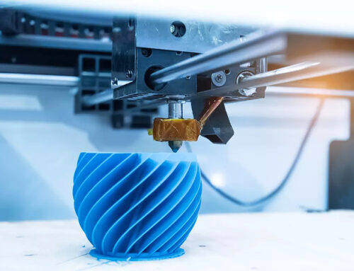
FDM (Fused Deposition Modeling) is one of the most widely used 3D printing technologies at present. Due to its low cost and wide range of material options, it is extensively employed for prototype production, tooling and fixtures, as well as small-batch manufacturing. However, to obtain parts with high strength, high precision, and qualified surface quality, merely adjusting the printing parameters is not sufficient – the design stage already determines the success or failure of the printing process.
Based on industry practices and the latest technical literature, combined with our practical application cases, this article systematically explores the core key points and advanced techniques for FDM component design, helping you avoid common defects in the design stage and improve printing efficiency and product quality.
- I. Printing Direction: Determining Strength and Surface Quality
- II. Structural Design: Avoid Sagging, Bridging and Warping
- III. Holes, shafts and fits: Ensuring assembly accuracy
- IV. Optimization of Support Structures: Reducing Material Waste and Simplifying Post-Processing
- V. Material Properties and Design Compatibility
- VI. Slice Settings and File Export
- VII. Post-processing and Verification
I. Printing Direction: Determining Strength and Surface Quality
In FDM technology, the printing direction is the first and most crucial decision for designers. It determines how the “skeleton” of the part grows and directly influences its final performance.
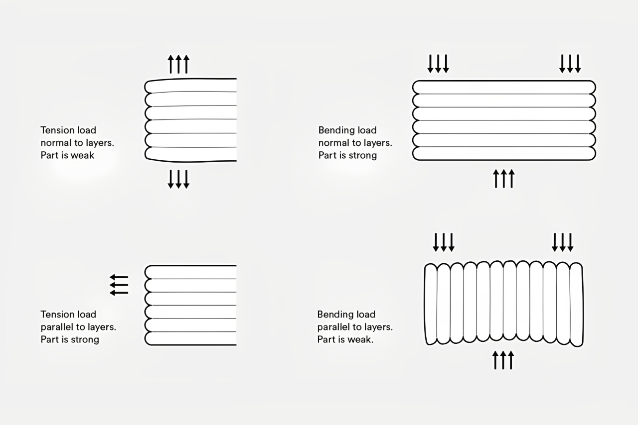
1. Align the main force direction with the layer lines
The fundamental characteristic of FDM parts is anisotropy – in the XY plane, the material is continuously extruded and thus has the highest strength; while in the Z-axis direction, the strength entirely depends on the thermal bonding force between one layer of plastic and the next, which is a natural weak point. Therefore, key force-bearing features (such as bolt holes, load-bearing walls) should be as parallel to the platform as possible to avoid layer separation, which means that a bent beam should be laid flat rather than standing upright; and for a tensile bolt hole, its axis should be perpendicular to the platform.
When operating the CAD software, ask yourself a question: “What forces are this part designed to mainly bear?” Then adjust the direction to ensure that these forces act within the layers instead of trying to tear the layers apart.
2. One-piece printing strategy
When your design includes gears, hinges, and other moving parts, printing them separately and then assembling them will possibly introduce alignment errors. The most ingenious method is to print them as a whole, but this requires extremely high design skills:
- Ensure that all moving parts are printed in the same direction to ensure consistency of all gaps.
- Use water-soluble supports such as PVA or HIPS to fill the gaps. After printing, dissolve them in a specific solution to obtain a fully functional mechanism that perfectly avoids the errors of manual assembly.
Case 1: Design Hacks Involving Force-Hanging Hinges and Large-Scale Base Plates
If the pin hole of a hinge is printed along the Z-axis, the weak interlayer adhesion of the hole wall makes it prone to cracking after repeated rotation. After evaluation, the designer opted to print the hinge flat, aligning the axis of the pin hole parallel to the build platform. In this orientation, the strength of the hole wall derives from the material continuity within the XY plane, increasing its shear resistance by 2–3 times and completely resolving the cracking issue. To maintain flexibility, we set the “Horizontal Expansion” parameter for the pin hole to -0.1mm in the slicing software, intentionally reducing the inner diameter of the hole wall to reserve an optimal clearance for the pin shaft.
When printing large-area base plates with ABS, the corners are prone to warping and detaching from the build platform due to material shrinkage. In one of our cases, the original base plate measured 150 mm×150 mm. In addition to using a heated bed, we designed grid-like grooves on the bottom surface of the part (1 mm wide and 0.5 mm deep). This not only significantly increases the adhesion area to the platform, much like how tire treads improve grip, but these small ribs also effectively suppress overall shrinkage deformation. If modifying the model is not feasible, enabling the Brim function generates a 5 mm wide single-layer skirt around the part, anchoring it firmly to the platform like a hold-down clip, which can be peeled off after printing.
II. Structural Design: Avoid Sagging, Bridging and Warping
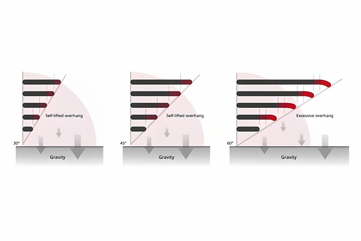
1. Keep Overhang Angles Below 45°
FDM printing is a layer-by-layer accumulation process. When the tilt angle exceeds 45°, the overhanging part lacks sufficient support from the layer below, and the incompletely cooled plastic will sag under gravity, leading to rough edges, decreased accuracy, and even print failure. Improvement approach: For non-critical appearance surfaces, the angle can be appropriately relaxed to 50°, but potential quality loss must be accepted; for important surfaces, it is recommended to add transition fillets (suggested R ≥ 2mm) to decompose a single large-angle overhang into multiple small-angle inclinations, improving molding stability; for complex overhang structures, they can be split into multiple components for printing and then assembled, avoiding the use of supports.

2. Keep Bridging Length within 10 mm
Bridging refers to the horizontal printing without support between two existing supports. When the bridging span exceeds 10mm, the material in the middle section cannot be cooled in time and will obviously sag under its own weight, forming an arc-shaped depression.
- Short bridges within 5mm can usually achieve good forming by increasing the rotation speed of the cooling fan;
- For medium spans of 5–10mm, it is recommended to enable “bridge detection” in the slicing software and appropriately reduce the printing speed for that section;
- For long spans exceeding 10mm, auxiliary support columns should be pre-designed in the model, or the structure should be changed to an inclined arch form, converting the bridge into a self-supporting structure.
3. Uniform Wall Thickness & Minimum Wall Thickness
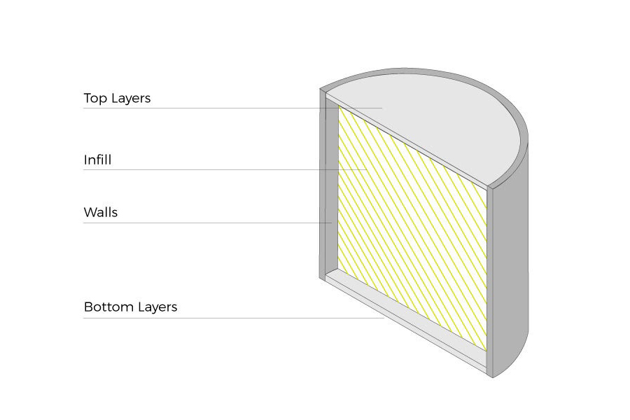
Wall thickness directly affects the success rate of printing and the performance of the part. Excessively thin walls (<0.8mm) will cause poor interlayer bonding and easy warping; while overly thick walls will increase material cost, printing time, and cause internal stress due to uneven internal cooling, and even cracking.
Our 3 key recommendations:
- The minimum wall thickness should be 2-3 times the nozzle diameter, usually 1.0-1.5mm is a safe range;
- Set R1-R3 fillets at the wall thickness transition points to effectively disperse stress and avoid sharp corners becoming the crack initiation points;
- For large flat areas, it is recommended to use grid-like reinforcing ribs instead of simply increasing the wall thickness, ensuring stiffness while reducing weight and minimizing shrinkage.
Our Cases on Structural Design:
Case 2: Optimizing Interlayer Strength in Gears
A task of printing a gear sample. Because the gear is subjected to cyclic shear force during transmission, if the printing direction makes the gear surface perpendicular to the build platform (Z-axis), the interlayer bonding surface is prone to peel off under the torque.
Our solution: Place the gear axis vertically to the platform, making the gear surface parallel to the XY plane, ensuring that the shear force acts on the direction with the highest material strength; Set the root radius of the gear corner to ≥0.5mm, significantly reducing the stress concentration in this critical area; When the gear diameter exceeds the build platform, design it to be split in half along the axis direction. The joining surface adopts the “dowel & adhesive groove” structure: The dowel head ensures alignment accuracy, while the groove accommodates sufficient glue to form a firm bonding layer, and finally, a pin is driven in perpendicular to the joining surface to provide mechanical interlocking, ensuring the reliable transmission of the torque.
Case 3: Support Strategy for Bracket-Type Parts
In the original design, a bracket featured an overhanging arm with a 60° inclination. Printing it as a single piece would require extensive support structures for this arm. Due to the numerous contact points, the supported surface would inevitably end up rough, compromising both appearance and assembly accuracy. After the first print, we modified the original design, changing the extended arm to a 45° inclined support + transverse reinforcement ribs, reducing the overhang angle to 30°, achieving self-support; Add a 3mm fillet at the junction between the arm and the main body to avoid stress concentration and potential interlayer cracking.
If certain parts of your component must be printed vertically due to spatial constraints, we recommend avoiding traditional linear supports and opting instead for “tree supports.” The intelligent generated dendritic structure only supports the key points at the lower edge of the suspended structure through point contact, which can reduce the supporting contact area by more than 60%. This significantly improves the surface quality of the supporting surface, and also significantly reduces the post-processing time and difficulty.
III. Holes, shafts and fits: Ensuring assembly accuracy
The inherent nature of FDM printing determines that it cannot achieve perfect dimensional accuracy like CNC or injection molding. Extrusion expansion, layering effect and material shrinkage all affect the final size, especially when it comes to the holes and shafts that need to be fitted together. Understanding and compensating for these deviations is the key to achieving smooth assembly.
1. Hole Size Compensation
Due to extrusion expansion, designing circular holes at the nominal size will likely result in a smaller size after printing. This is because the molten plastic is extruded from a circular nozzle and has a natural “rebound” and “spread” effect, causing the inner diameter of the hole to contract. The hole diameter should be enlarged by 0.2–0.3 mm during design. For example, if you need an M5 bolt to pass through easily, design the hole as Ø5.3 mm instead of Ø5.0 mm. It should be noted that the shrinkage rate of different materials is different. The shrinkage rate of ABS is usually higher than that of PLA, so for ABS parts with strict size requirements, the compensation amount may need to be taken to the upper limit or slightly increased.
2. Shaft-Hole Fit Clearance
“Zero tolerance” fits are almost impossible to achieve in FDM. Our goal is to design a clearance that not only meets the function but also facilitates assembly.
Clearance Fit (most common): Requires the shaft to rotate or slide freely within the hole. We recommend a unilateral clearance of 0.1–0.2 mm (i.e., a total diametral clearance of 0.2–0.4 mm). This range is sufficient to counteract printing errors while avoiding excessive play.
Interference Fit (press-fit): We hope that the shaft and the hole are closely combined through pressure. In FDM, excessive interference will directly cause the weakest interlayer bonding surface to crack. Our experience is that the interference should not exceed 0.15 mm, and the press-in depth should not be too deep. For high-strength press-fit structures that require high strength, we prefer to print a slightly looser hole and then fix it by applying epoxy resin, which is more reliable.
3. Minimum Diameter for Vertical Pins/Rods
Vertically printed thin pins or rods are very fragile because their height is formed by the stacking of hundreds or thousands of weak interlayer bonding points. Lateral forces can easily cause them to break at some layer seam.
Any non-load-bearing locating pins should have a minimum diameter of 1.0 mm; for those that need to withstand light loads, the diameter should be at least 2.0 mm.
If the diameter must be smaller than this, some reinforcing features need to be designed to compensate for the weakness. The most effective and simplest reinforcement method is to add a 0.5-1 mm fillet at the connection between the thin pin and the base to distribute stress; if the structure allows, designing the thin pin at an angle (such as 30°) to the vertical direction can form a more stable “natural support” during printing, resulting in strength far exceeding that of vertical printing.

Case 4: Shaft-Hole Clearance Fit
We once had a project where we needed to design a Ø6 mm sliding bearing for a PLA mechanism. The initial design used an “ideal” zero-to-zero fit, but the shaft and the hole could not be assembled at all. Forced pressing caused the hole wall to crack. Due to extrusion expansion, layering effect accumulation, etc., the actual hole diameter was 0.1–0.3 mm smaller than the design expectation as we have mentioned before. Therefore, we decided to use experimental data to guide the design. The following table shows the average values measured after printing test pieces using PLA material, a 0.4 mm nozzle, and a 0.2 mm layer height:
| Design Hole Diameter (mm) | Actual Average Hole Diameter (mm) | Recommended Design Value (mm) |
| 5.0 | 4.82 | 5.3 |
| 10.0 | 9.75 | 10.3 |
Based on this, we have summarized the empirical formulas applicable to our equipment (or as a reference to you):
- Clearance Fit: Hole Diameter = Shaft Diameter + 0.3 mm (PLA) / 0.4 mm (ABS)
- Interference Fit: Shaft Diameter = Hole Diameter + 0.1 mm (only suitable for short travel press-in)
For similar reasons, directly printing M3 internal threads is prone to difficulty in screwing due to layer misalignment. Consider the following two solutions: Design a Ø2.5 mm pilot hole, and after printing, use an M3 tap to thread it. This not only solves the issue of hole diameter but also results in higher thread strength; or change the thread profile to a trapezoidal tooth (tooth tip width≥0.4 mm), and set a 45° chamfer at the start of the thread to avoid the first thread from chipping.

IV. Optimization of Support Structures: Reducing Material Waste and Simplifying Post-Processing
Support structures are a challenge that FDM designers must confront. Our goal is not to eliminate them completely, but to minimize their negative impact through intelligent design.
1. Self-supporting design
When feasible at the design level, over 45° overhangs can be modified to smooth slopes≤45° (according to the “45° rule”, a 60° overhang requires support, while a 45° slope can often achieve perfect self-supporting); or replace horizontal bridging with arched structures; or replace large areas of solid overhangs with diamond-shaped or honeycomb-shaped hollow grids. These structures inherently possess sufficient stiffness and self-supporting properties, fundamentally eliminating the need for supports.
2. Minimizing the Contact Area of Supports
As we have mentioned in case 3, in areas where support must be added, the “tree-like support” (Tree Support) is preferred. This is because compared to traditional straight support, tree-like support is like growing branches and can precisely support the overhanging area with the minimum contact points. This typically reduces the contact area of support by over 60%, making the subsequent removal easy and fast, and significantly improving the surface quality of the support surface. For critical and isolated overhanging points, a small, easily breakable sacrificial support column can be directly designed in the original CAD model. This gives designers full control over the position and form of the support, avoiding the unpredictability of support generation by slicing software.
V. Material Properties and Design Compatibility
1. Common Materials for FDM 3D Printing
The top three commonly used materials in FDM printing are PLA, ABS, and PETG. Each material has its own distinct characteristics, and designers need to consider the function of the component and project requirements when making a comprehensive decision.
PLA is easy to print due to its low shrinkage rate and excellent build plate adhesion to the build plate, making it ideal for display models with rich details. However, its brittleness and poor thermal stability (softening begins at approximately 60°C) limit its use in functional parts and outdoor applications. Our experience shows that PLA is a perfect prototyping material but is rarely used as a final load-bearing component.
ABS has good strength and excellent heat resistance, but its significant shrinkage rate is the primary enemy to consider during design. This requires us to mitigate risks in design by actively breaking down large continuous planes into grid structures with reinforcing ribs; and adding fillets with a radius of at least R3 at all corners to resist stress concentration from shrinkage; additionally, using a heated print bed and enclosed print chamber to provide a stable, wind-free environment to prevent cracking and warping caused by uneven cooling.
PETG strikes a balance between the printability of PLA and the toughness of ABS, while also offering strong chemical resistance. However, its inherent “stickiness” during printing may cause nozzle stringing and surface blobbing. To address these issues, our solution is to enable and optimize the retraction settings in the slicer and appropriately increase the nozzle starting speed to cut off the filament strands and achieve a cleaner surface.
2. Text and Surface Engraving
When adding text or logos to a product, printing directly at the default size in CAD often yields unsatisfactory results. For raised embossed text, both the height and stroke width should be no less than 1.0mm. Fine strokes may become blurred due to layer lines. For recessed engraved text, the depth in the design should be at least 0.5mm and the width no less than 1.0mm to ensure sufficient depth to accommodate layer lines and keep the texts legible. However, whether it is embossed or engraved, sans-serif bold fonts should be used, and ample spacing should be left between strokes to prevent plastic accumulation and blurring.


VI. Slice Settings and File Export
Two key parameters require particular attention during file preparation to ensure model integrity and surface quality:
- The model must watertight (manifold): Before exporting the STL, check if the model has non-manifold edges, self-intersections, or surface gaps. You can use “3D Print Toolbox” (Blender) or “Netfabb” to automatically repair them.
- Chord Height determines surface quality: Chord Height determines the accuracy of surface approximation when converting smooth NURBS surfaces from CAD to STL’s triangular mesh format. This parameter defines the maximum permissible deviation between the original curve and the tessellated representation.
For high-visibility surfaces and precision cylindrical fits, we specify a chord height of 0.01mm to achieve near-perfect surface continuity, accepting the resulting larger file size. For most functional components and internal structures, a 0.05mm chord height achieves the optimal balance between accuracy and processing efficiency, producing visual results indistinguishable from finer settings while maintaining manageable file sizes.
VII. Post-processing and Verification
1. Splitting Large Components
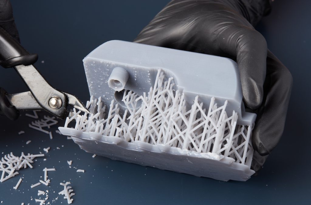
Part splitting becomes necessary when component dimensions exceed printer build volume, internal supports cannot be removed, or when material optimization is required. However, we never split models arbitrarily. The critical factor lies in designing positioning tenons, interlocking structures, or alignment pin holes at the separation surfaces. This ensures assembly accuracy and enables the reassembled part, through bonding (PLA/ABS specific adhesive, epoxy) or bolting, to regain or even exceed the strength of a single printed piece.
2. Heat Treatment and Mechanical Strengthening
- Heat Treatment Strengthening: For ABS or PETG parts that bear loads, we sometimes use the annealing process – placing the parts in a specific temperature (below the glass transition temperature) oven and slowly heating and cooling them. This can restructure the molecular structure of the material, significantly enhancing the interlayer bonding strength and overall rigidity.
- Surface Finishing: For components requiring professional appearance, we implement a standardized process: progressive dry/wet sanding (180 to 2000 grit sandpaper) → high-build primer spraying → fine sanding → top coat painting. Through this treatment, FDM parts can achieve surface smoothness comparable to injection molded components.
FDM 3D printing is a systematic engineering process that involves from the design stage. By following the above design principles, you can obtain printed components with excellent strength, precision and appearance under the conditions of low cost and short cycle. The suggestions presented in this article are based on the latest industry guidelines and our measured data, and are applicable to the majority of desktop and industrial FDM devices. We hope these can provide solid references for your next design. Please feel free to leave a message to obtain more knowledge, or contact our team directly at sales@kingstarmold.com to obtain a quote for your project.
