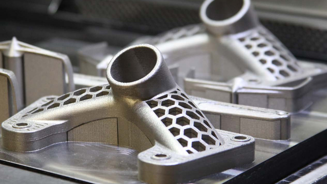
Direct Metal Laser Sintering (DMLS) is a powerful additive manufacturing technology that uses a high-powered laser to fuse fine metal powders into solid metal parts, layer by layer. This 3D printing process allows for the creation of complex geometries and high-performance metal components that are often difficult or impossible to produce using traditional manufacturing methods.
DMLS stands out for its ability to produce fully functional metal parts directly from CAD data, without the need for costly molds or tooling. It offers several key benefits, including:
- Design Flexibility: DMLS enables the production of intricate designs, such as internal cavities, lattice structures, and complex geometries that traditional methods cannot achieve.
- Rapid Prototyping and Production: DMLS allows for quick iteration, enabling faster development of parts for testing and production, often reducing lead times from weeks or months to just days.
- Material Efficiency: DMLS uses metal powders, and the additive nature of the process ensures minimal waste, contributing to both cost savings and sustainability.
- Customization: Whether for low-volume production runs or highly specialized components, DMLS offers customization options without the need for expensive tooling changes, making it ideal for industries like aerospace, medical, and automotive.
By leveraging these advantages, manufacturers can not only streamline production but also unlock new possibilities for part design and functionality, making DMLS a go-to solution for advanced metal part manufacturing.
1. What is DMLS?
Direct Metal Laser Sintering (DMLS) is an advanced form of additive manufacturing (AM) that specifically focuses on producing high-quality, functional metal parts. The DMLS process uses a laser to selectively fuse fine metal powders layer by layer to create solid metal objects based on 3D Computer-Aided Design (CAD) data.
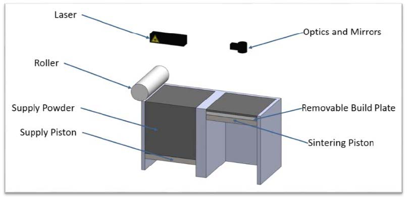
1.1 How DMLS Works
The DMLS process begins with a 3D CAD model of the part to be produced. This model is sliced into thin layers, which will be built up sequentially. The laser then selectively fuses the metal powder particles, using the precise heat from the laser beam to melt the powder in a controlled pattern.
Here’s a breakdown of the DMLS process:

Step 1: Material Feed
Fine metal powders (such as stainless steel, titanium, aluminum, and others) are carefully fed into the build chamber of the DMLS machine. The material is selected based on its compatibility with the laser sintering process and the specific requirements of the part being produced.

Step 2: Adding a Layer
A thin, uniform layer of metal powder is spread across the build platform. The thickness of each layer typically ranges from 20 to 100 microns, depending on the material and the resolution required for the part.

Step 3: Sintering
A high-powered laser scans the metal powder layer, focusing on specific areas to melt and fuse the particles according to the digital design. The laser’s precise control allows for complex and detailed geometries to be created with high accuracy.

Step 4: Piston Movement
After sintering a layer, the build platform lowers slightly. This piston-like movement helps to create space for the new layer of powder to be spread evenly across the build platform, ensuring the consistent addition of material for each subsequent layer.

Step 5: Layering
A new layer of metal powder is added on top of the previous one, and the sintering process is repeated for each layer. Each layer is bonded to the one below it, building the part layer by layer until the entire geometry is complete.

Step 6: Part Removal
Once the part is fully constructed, it is allowed to cool. After cooling, the finished part is carefully removed from the build platform. Additional post-processing steps may be necessary, such as machining, heat treatment, or surface finishing, depending on the material and intended use of the part.
The ability to create complex geometries, including internal features and intricate details, makes DMLS an ideal solution for industries where traditional manufacturing methods fall short.
2. Key Advantages of DMLS for Metal Parts
Direct Metal Laser Sintering (DMLS) offers numerous advantages over traditional manufacturing techniques, making it a preferred choice for producing high-performance metal parts. The key benefits include speed, design flexibility, and material versatility, which together enable a more efficient and cost-effective production process.
2.1 Speed and Efficiency in Part Production
One of the most significant advantages of DMLS is its rapid production capability. Traditional manufacturing processes, such as machining or casting, can take weeks or even months to produce parts, especially when tooling is involved. In contrast, DMLS allows parts to be produced in a matter of days—often between 1 to 3 days—depending on the complexity and size of the part.
Since DMLS doesn’t require tooling or molds, the upfront costs are significantly lower, and the production time is much faster. Additionally, DMLS is ideal for short runs, prototyping, or low-volume production, where traditional methods would be too expensive and time-consuming.
2.2 Capability for Complex Geometries and Reduced Part Count
DMLS is especially well-suited for creating highly complex parts that would be difficult or impossible to achieve with traditional manufacturing methods. It allows engineers to design parts with intricate internal features, hollow geometries, and geometries with overhangs that often require additional assemblies or tools in traditional methods. This ability to consolidate multiple parts into a single, complex design reduces the overall part count, assembly time, and potential for errors.
For example, a part that might traditionally require several components to be assembled can be built as a single piece in DMLS, streamlining the design and reducing the need for external fasteners or joints.
2.3 Material Options Available
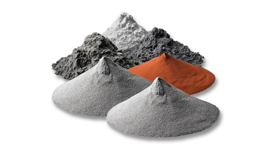
DMLS offers a broad range of material options, including metals that are difficult to machine with conventional methods. Some commonly used materials include:
- Stainless Steel: Known for its durability, corrosion resistance, and strength, stainless steel is a popular choice for a variety of industries, including aerospace, automotive, and medical.
- Titanium: A lightweight, high-strength material with excellent corrosion resistance, titanium is often used in aerospace, medical implants, and high-performance industrial applications.
- Cobalt Chrome: A material known for its hardness and wear resistance, cobalt chrome is commonly used in industries such as medical and dental devices, as well as in turbine blades for aerospace.
These materials, among others, allow manufacturers to select the best option based on performance needs, durability, and cost, ensuring that parts are fit for their intended purpose.
In summary, DMLS’s speed, capability for complex part designs, and material variety make it an ideal solution for a wide range of applications, from rapid prototyping to end-use parts production.
3. Typical Applications of DMLS
Direct Metal Laser Sintering (DMLS) has revolutionized the way metal parts are produced, offering significant advantages for industries that require high-precision and complex geometries. From aerospace to medical devices, DMLS is widely utilized across various sectors due to its versatility, efficiency, and ability to produce custom, high-performance parts.
3.1 Common Industries Utilizing DMLS
DMLS is used in several industries that demand rapid production of metal parts with intricate designs. Some of the key industries benefiting from DMLS include:
- Aerospace: The aerospace industry relies on DMLS for the production of lightweight, durable, and high-strength components. The ability to manufacture complex geometries with internal channels for cooling or weight reduction is crucial for creating parts like turbine blades, brackets, and structural components. DMLS significantly reduces material waste, making it ideal for the production of highly specialized parts that would otherwise be expensive and time-consuming to create.
- Medical Devices: DMLS is extensively used in the medical industry to create custom implants, surgical tools, and prosthetics. Titanium, in particular, is a popular material for medical applications due to its biocompatibility and strength. DMLS enables the creation of customized implants tailored to the unique anatomy of patients, reducing the need for mass-produced, off-the-shelf solutions.
- Automotive: In the automotive sector, DMLS is used for both prototyping and low-volume production of functional parts. Components such as engine parts, brackets, and customized tooling can be produced quickly and with high accuracy. The flexibility of DMLS allows manufacturers to iterate designs rapidly and validate parts in real-world conditions before committing to full-scale production.
- Tooling and Industrial Equipment: DMLS is also widely used in producing tooling for manufacturing processes. Complex tooling with integrated cooling channels, for example, can be produced more easily with DMLS than with traditional machining. These advanced tools can improve efficiency and reduce costs in mass production environments.
- Consumer Goods: For industries like jewelry and fashion, DMLS offers the ability to create intricate, customized designs. Small, high-detail parts, such as custom jewelry pieces, are produced efficiently and can be personalized to meet individual preferences.
3.2 Examples of Parts Commonly Produced Through DMLS
The versatility of DMLS allows for the production of a broad range of parts across different industries. Here are some examples of parts that are commonly produced using DMLS:
- Aerospace Parts: Lightweight brackets, turbine blades, combustion chambers, and aerospace fasteners. These parts require high strength and heat resistance, which are achieved through materials such as titanium, stainless steel, and Inconel.
- Medical Implants: Custom knee, hip, and spinal implants, as well as dental implants. DMLS allows for patient-specific designs, improving fit and comfort while reducing surgery times.
- Automotive Components: Customized engine components like exhaust parts, turbochargers, and lightweight structural components. DMLS can also be used to create tooling inserts, prototypes, and performance test parts for automotive engineers.
- Industrial Tooling: Injection molds with integrated cooling channels, forming tools, and dies that require intricate features. The ability to build complex internal geometries improves cooling efficiency and part performance.
- Consumer Goods: Customizable products such as eyewear frames, jewelry, and high-fashion accessories. These can be designed with intricate details and produced quickly in small batches.
DMLS continues to grow in popularity for its ability to produce highly specialized, customized parts that meet the demands of industries with specific performance, strength, and durability requirements. The technology’s impact spans from rapid prototyping to end-use part production, driving innovation across multiple sectors.
4. Designing for DMLS: Best Practices
DMLS can use a range of metals, including Aluminum (AlSi10Mg), Stainless Steel (316L), Titanium (TC4), and Maraging Steel. Here are the specifics of its capabilities:
4.1 Overall Considerations
- Maximum Build Volume (Build sizes vary per material):
- Maraging Steel: 280mm x 350mm x 280mm (11.02″ x 13.78″ x 11.02″)
- Titanium (TC4): 200mm x 150mm x 150mm (7.87″ x 5.91″ x 5.91″)
- Stainless Steel (316L): 280mm x 350mm x 280mm (11.02″ x 13.78″ x 11.02″)
- Aluminum (AlSi10Mg): 400mm x 300mm x 400mm (15.75″ x 11.81″ x 15.75″)
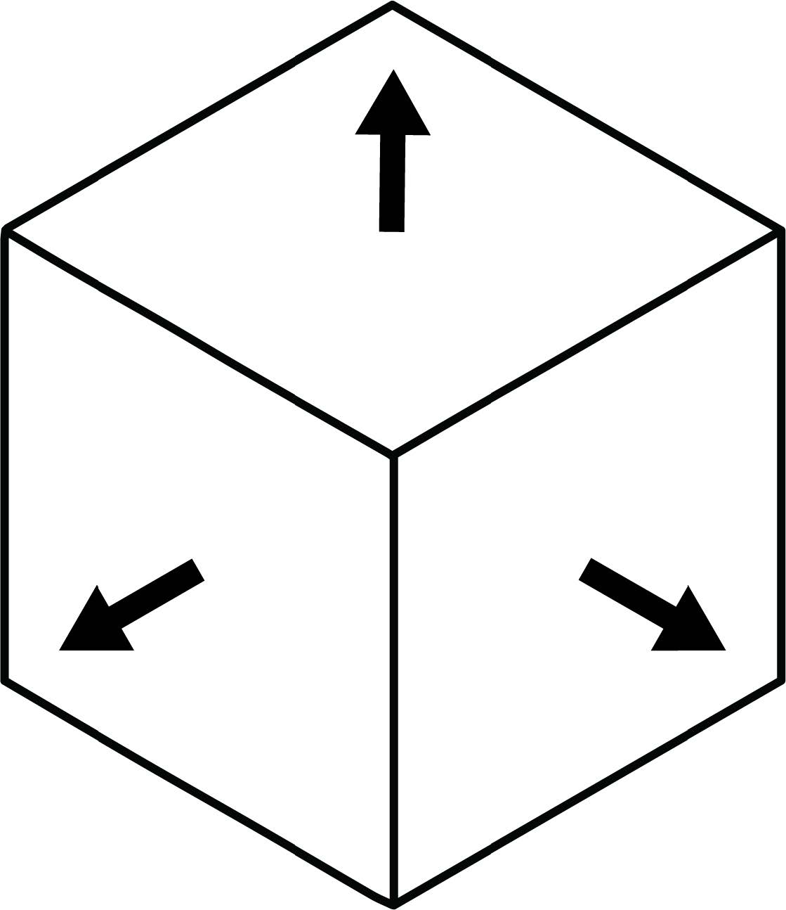
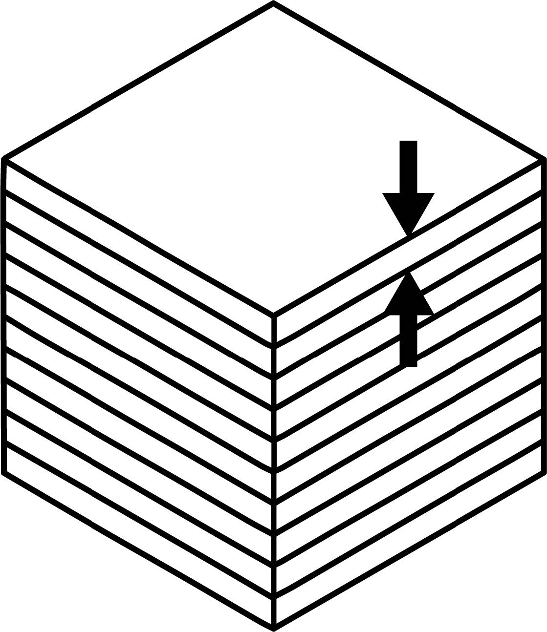
- Layer Height: 0.1mm (0.0039”), with a standard layer height of 100 microns, which is the resolution limit in the z-axis.
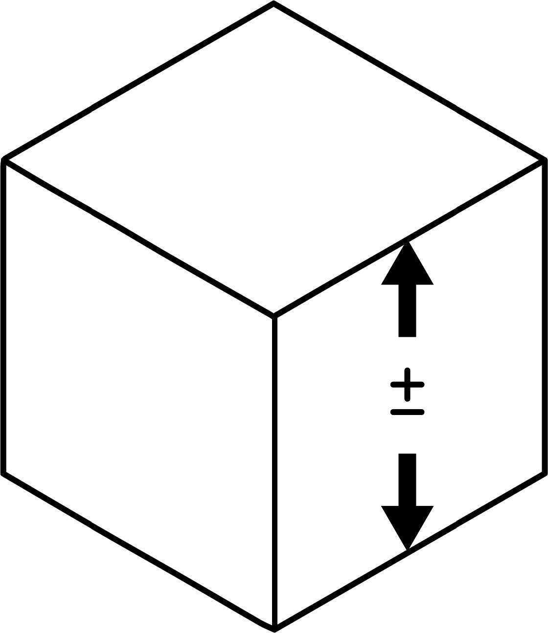
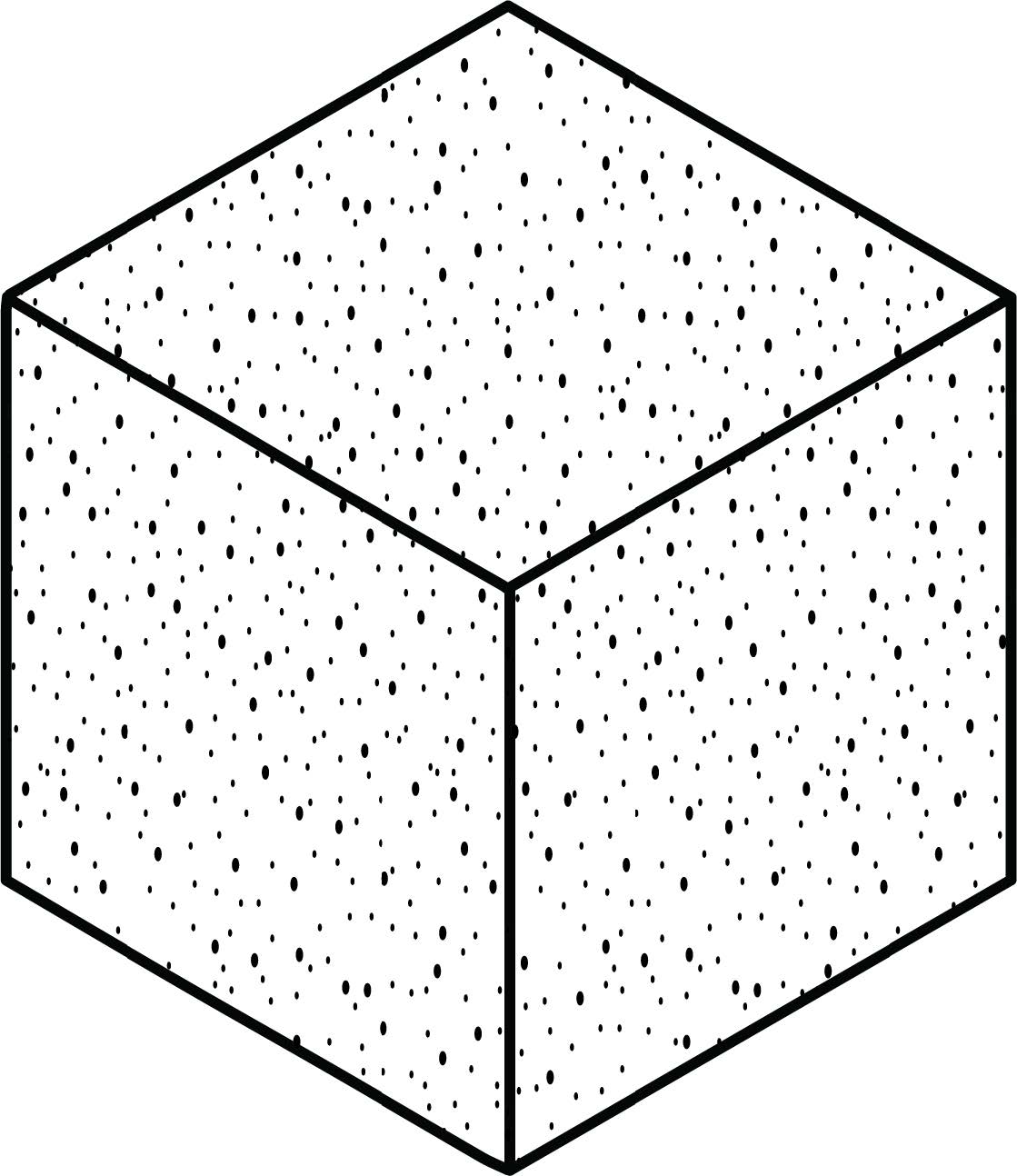
- Surface Finish: Geometry-dependent, with visible layer lines at low angles relative to the build plate. Post-processing includes shot peening to achieve a surface roughness of 200-400 Ra after support removal.
4.2 Key Design Considerations for DMLS
a. Wall Thickness
Wall thickness plays a critical role in the part’s strength and overall build success.
- Minimum Wall Thickness: 0.8mm (0.031”) for supported walls.
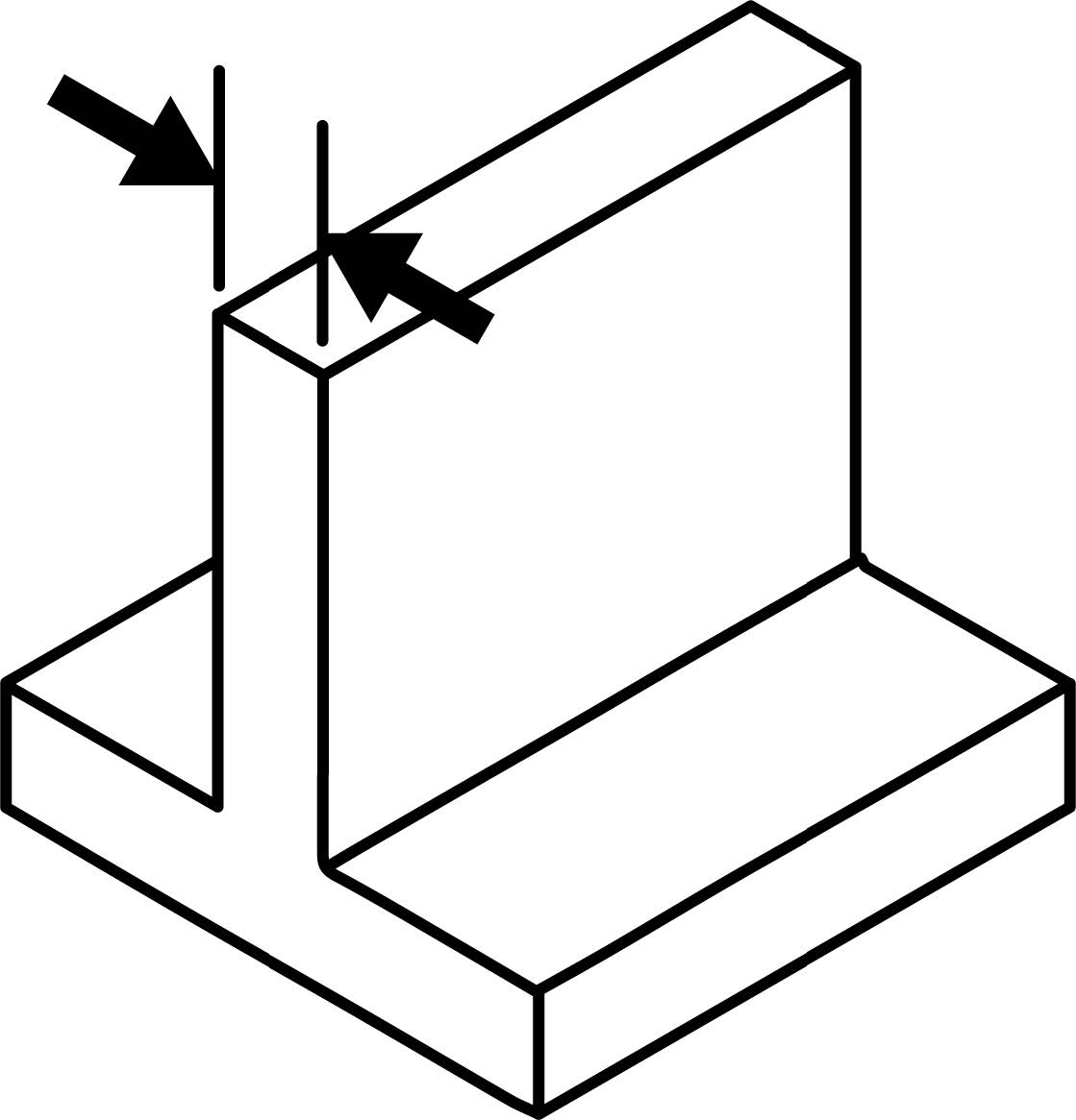
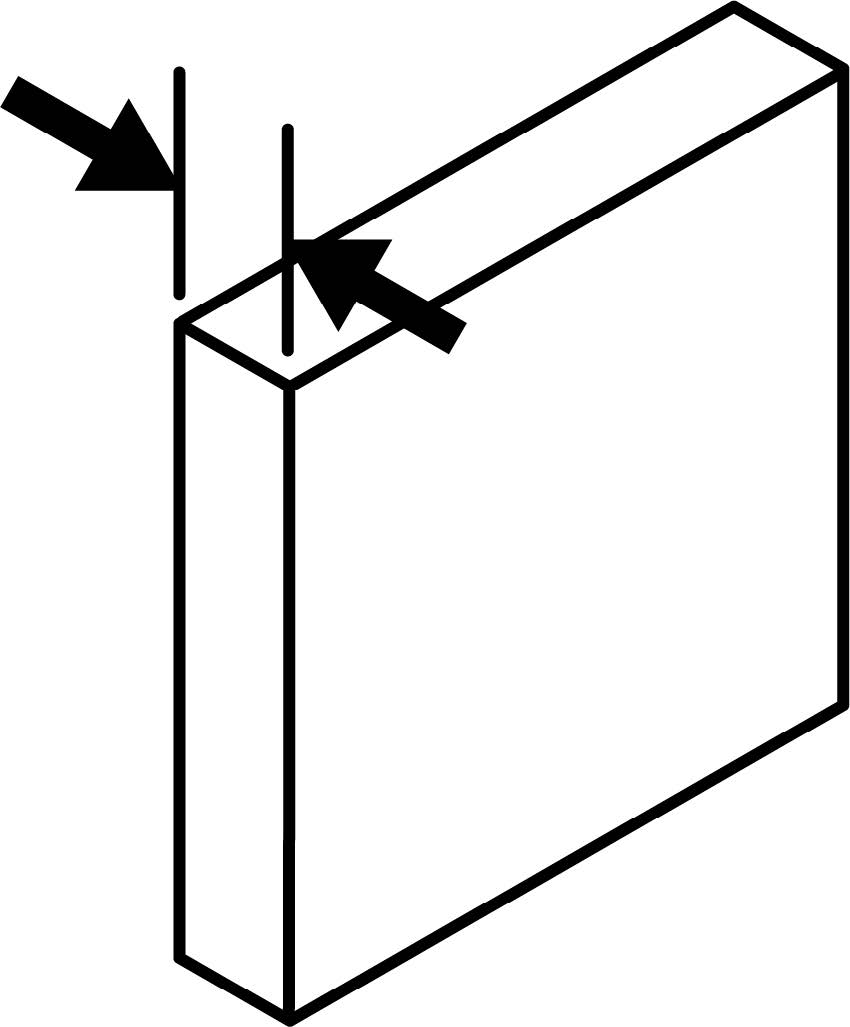
- Minimum Unsupported Wall Thickness: 1mm (0.039”), as unsupported walls are prone to warping or failure.
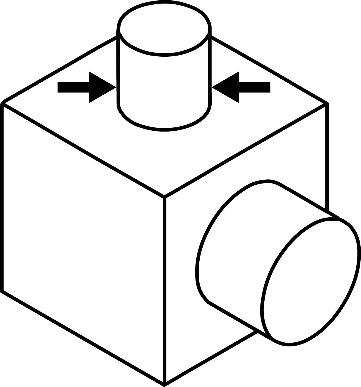
- Minimum Pin Diameter: 1.5mm (0.059″), the minimum pin size depends on a combination of parameters such as part orientation, diameter and length of the pin.
b. Minimum Detail Size
The quality of engraved and embossed features depends heavily on part orientation and the resulting thermal effects of printing. Try to place fine details away from overhanging faces that require support, since touchpoints can interfere with intricate geometry.
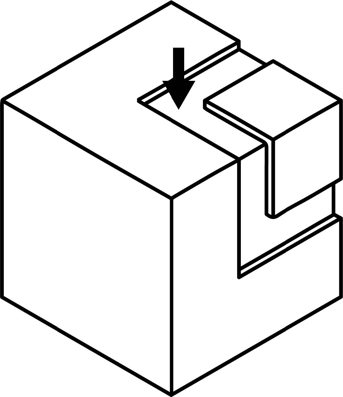
- Debossed Details: Minimum depth: 0.5mm (0.019″), debossed details are recessed features on your model. These features should be no shallower than 0.5mm (0.019″).
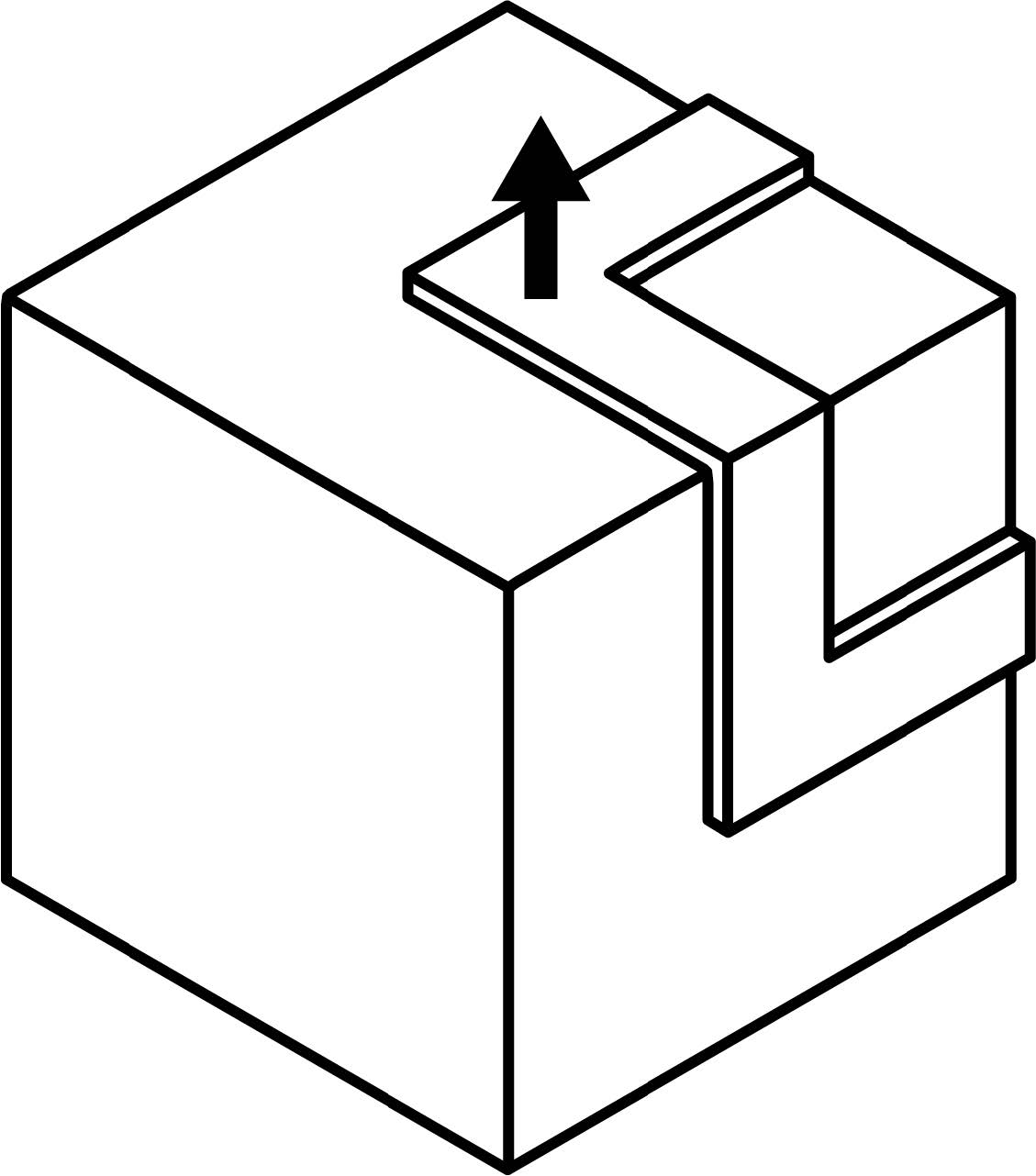
- Embossed Details: Minimum depth: 0.5mm (0.019″) Embossed details are raised features on your model. We recommend a thickness of 1mm (0.039”) & depth of 0.5 mm (0.019”)
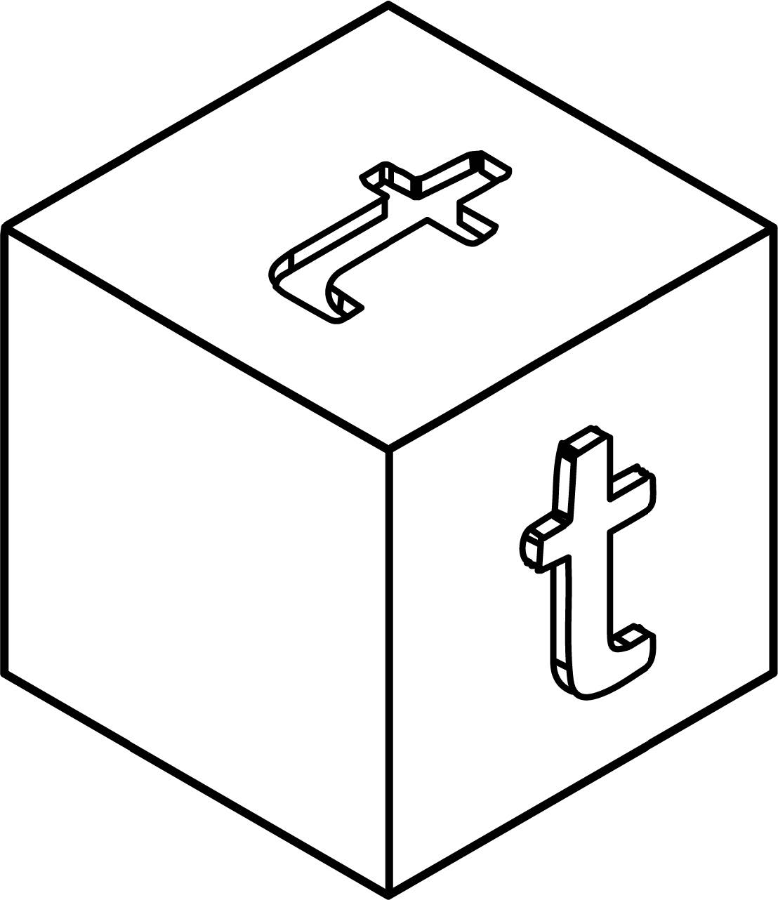
- Text: Minimum point size: 14pt 0.5mmminimumline thickness and 0.5mm depth or a minimum font size of 14 is suitable for every direction. Bold Sans Serif font is recommended.
c. Holes and Gaps
Hole accuracy can vary depending on print orientation, thickness of surrounding material and support structures. For tight tolerances, consider printing center marks and post-machining them instead.
- Minimum Hole Size: 1mm (0.039″). Holes less than 1mm are likely to fuse. Smaller holes can be post-machined.

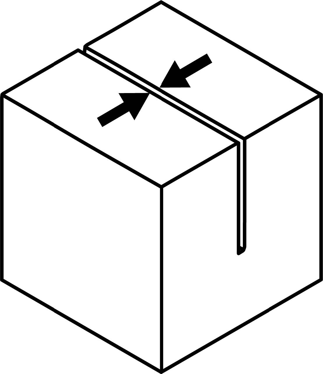
- Minimum Gap Size: 0.5mm (0.19″)
Wall thickness: 0.3mm (0.011”)- minimum gap width: 0.8mm (0.03”) Wall thickness: 3mm (0.11”)- minimum gap width: 1mm (0.04”) Wall thickness: 6mm (0.22”)- minimum gap width: 1.2mm (0.047”)
- Minimum Escape Hole Size: 4mm (0.15″). Hollow walls and enclosures will be filled with metal powder, and must be designed with escape holes so that the powder can be removed during cleaning.

d. Design for Complex Geometries
DMLS allows for highly complex shapes and structures.
-
- Incorporate internal channels, lattice structures, and other complex features, which are difficult or impossible to produce using traditional methods.
- Use lightweight and hollow structures to reduce material usage and simplify support needs while maintaining strength.
e. Part Geometry
Part geometry can be optimized for 3D printing to reduce material usage, increase strength and rigidity, and take advantage of machine capabilities.
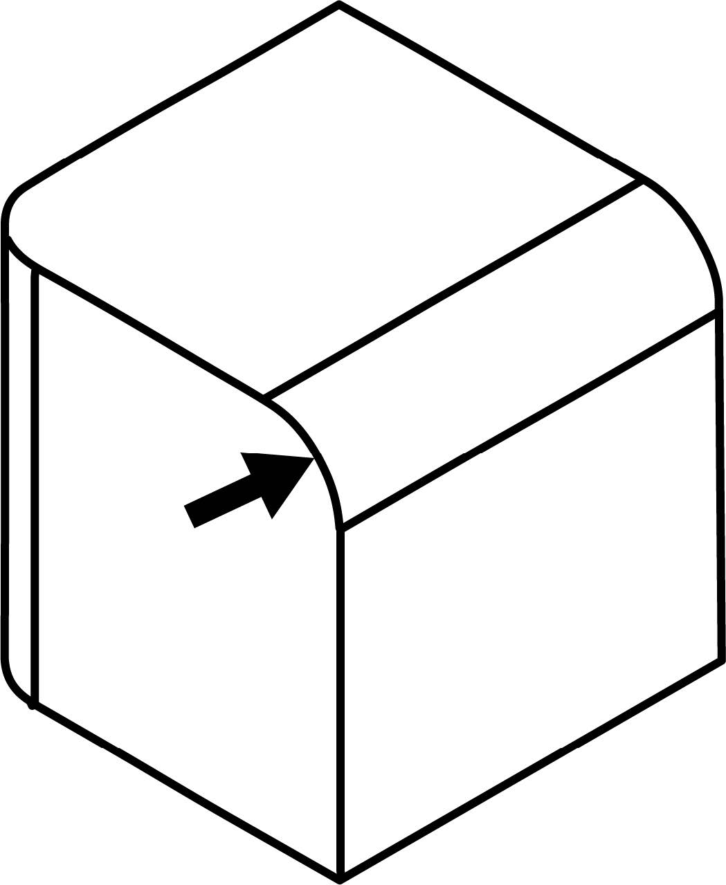
- Fillets: Fillets can be used to reduce stress concentrations and increase the strength of your part. When designing fillet features across inside and outside corners, it is best to have them share a common center point in order to maintain a consistent wall thickness.
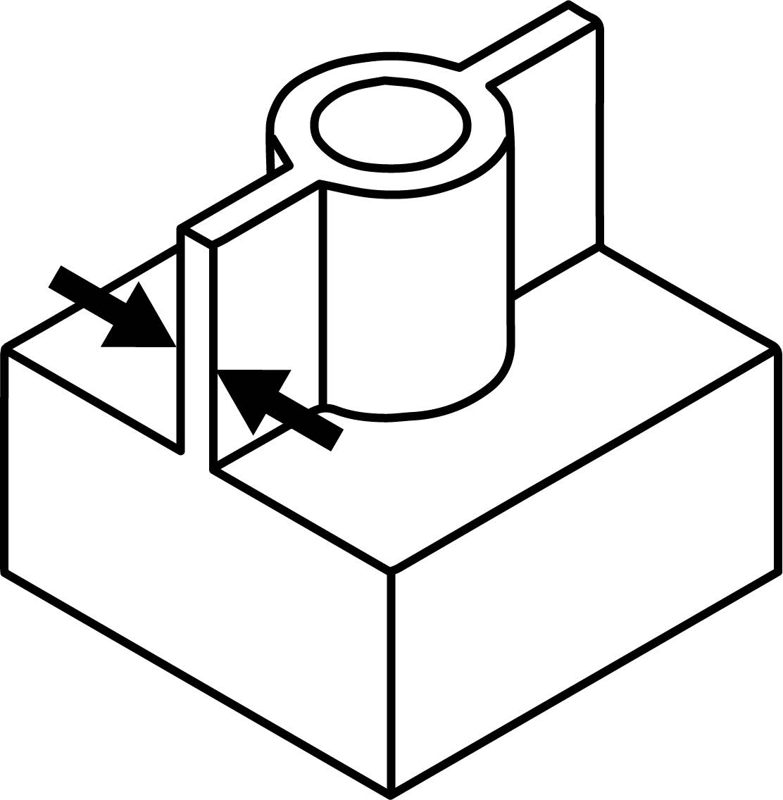
- Bosses and Ribs: Bosses and ribs are an effective way to add strength and stiffness to a part while keeping material consumption to a minimum, this can also reduce build time and use less support material.
- Support Structures: DMLS parts are partially supported by surrounding powder, but also require printed supports to counteract their increasing weight as they print. These supports are made with the same material and must be removed with metal cutting tools, which may affect the surface finish.
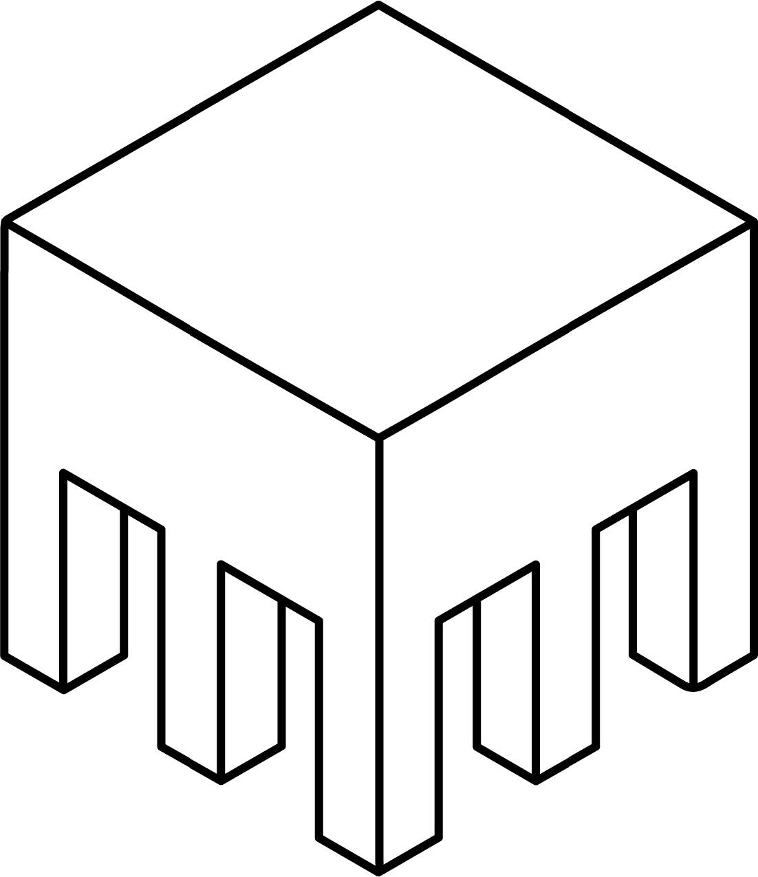

- Infill: Not applicable for DMLS.
f. Clearances and Fits
The mechanical performance of printed assemblies is sensitive to variables like print orientation, layer height, and machine tolerances.
- Minimum Clearance: 0.5mm (0.019”) for moving parts such as hinges or joints.
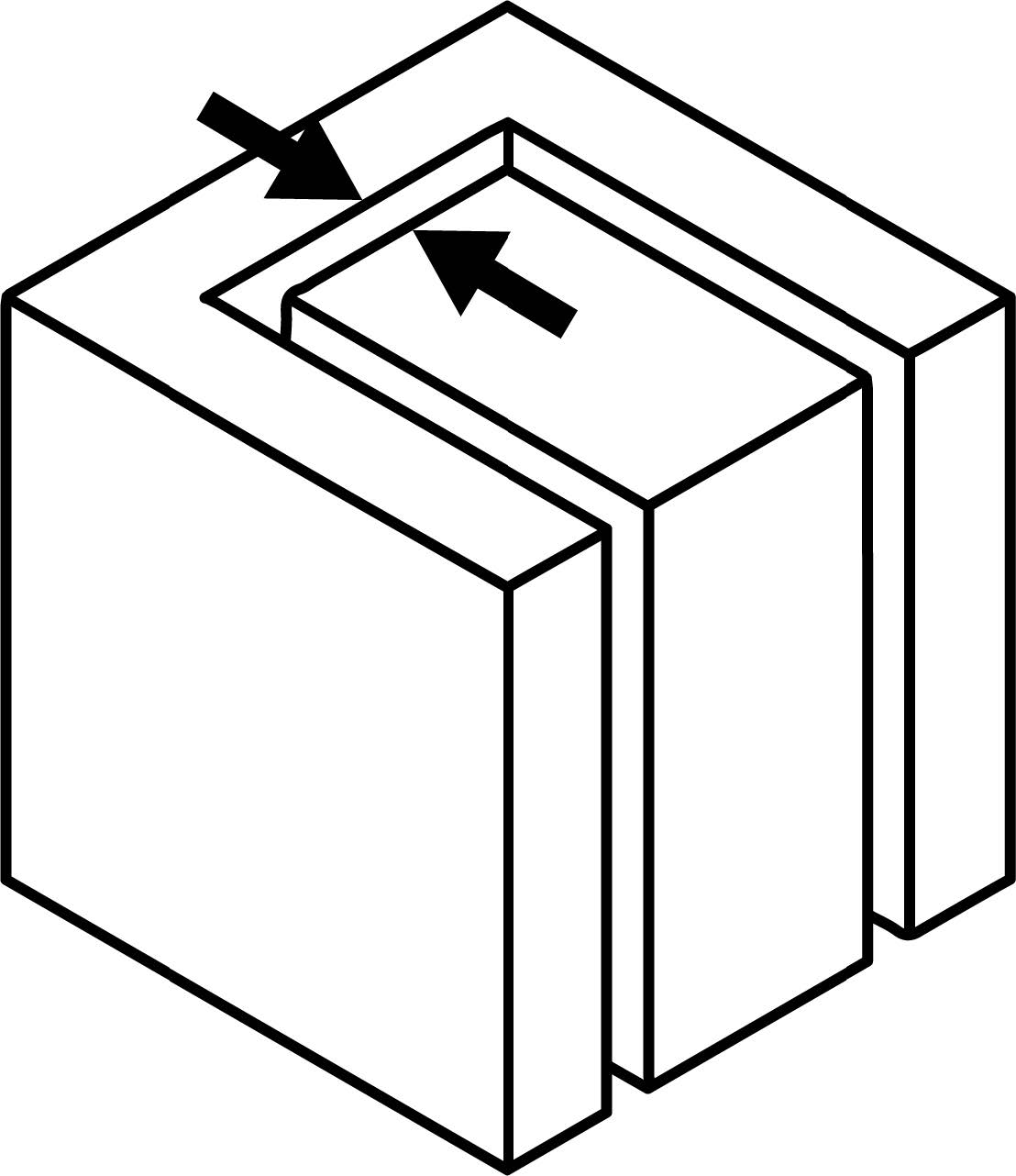
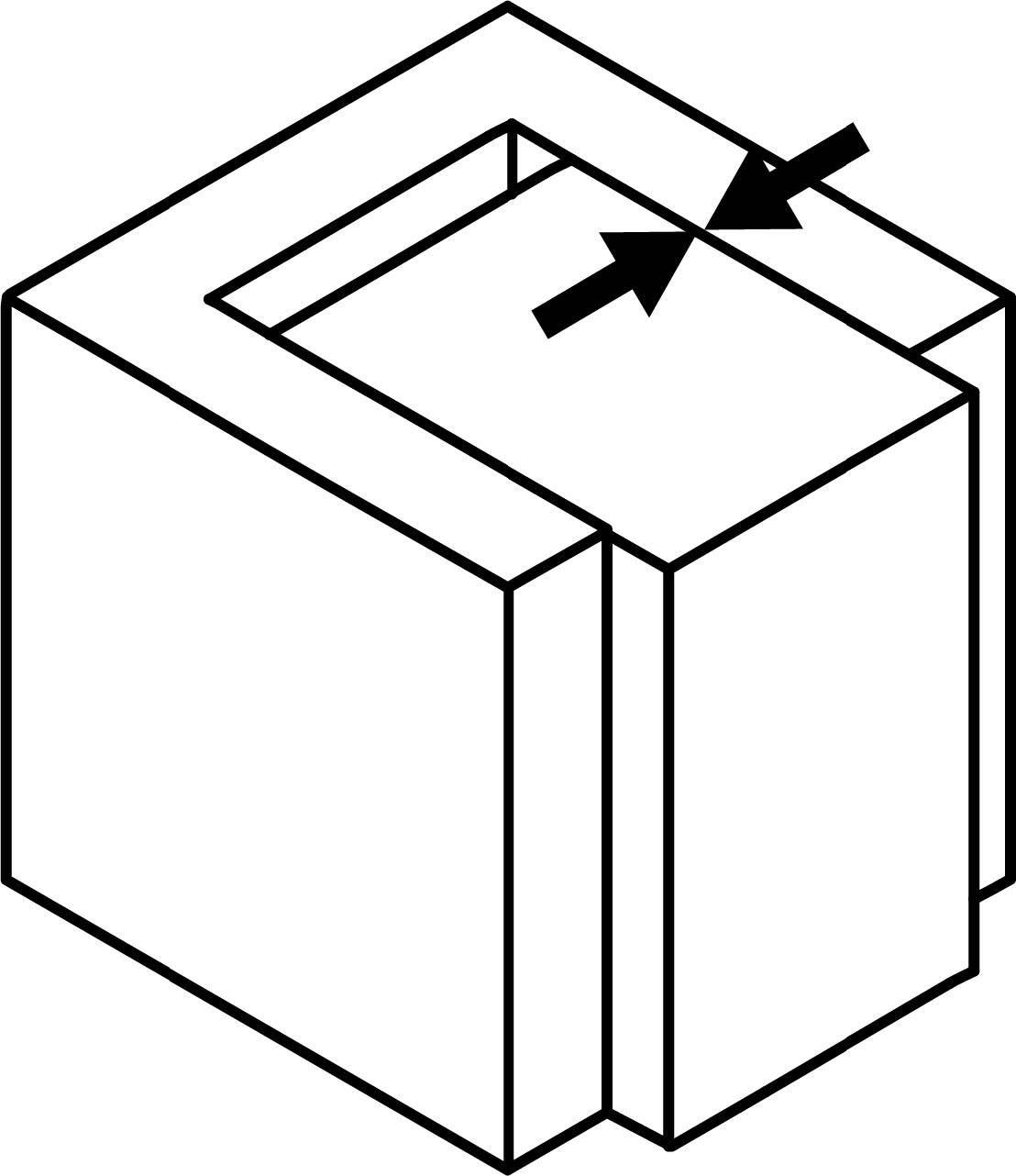
- Press Fit: For a tight press fit, ensure a 0.3mm (0.011”) offset, with chamfers at the leading edges.
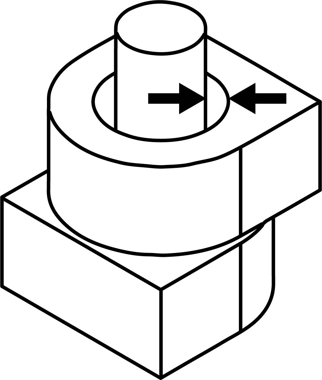
- Printed Linkages: 0.6mm (0.023″), this defines the minimum allowed gap between a bush and a bolt, to avoid bonding of the hinge parts.
g. Threads and Inserts
Threads can be printed directly but may not guarantee functionality; consider tapping after printing for better accuracy. Avoid printing hardware, as it may not be as precise as machining.
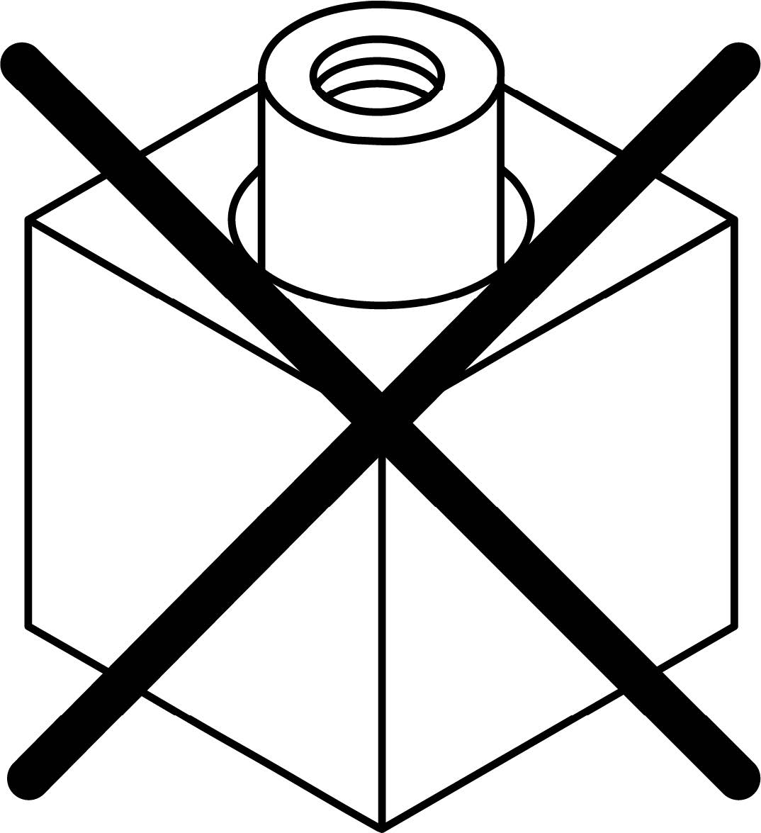
- 3D Printed Threads: Print vertically or design for tapping. Threads can be sintered directly into parts depending on the size of the thread and print orientation. Threaded sections should be printed vertically and should have sufficient clearance to allow a tap or die to be used. Smaller threads should be left to be drilled and tapped rather than printed.
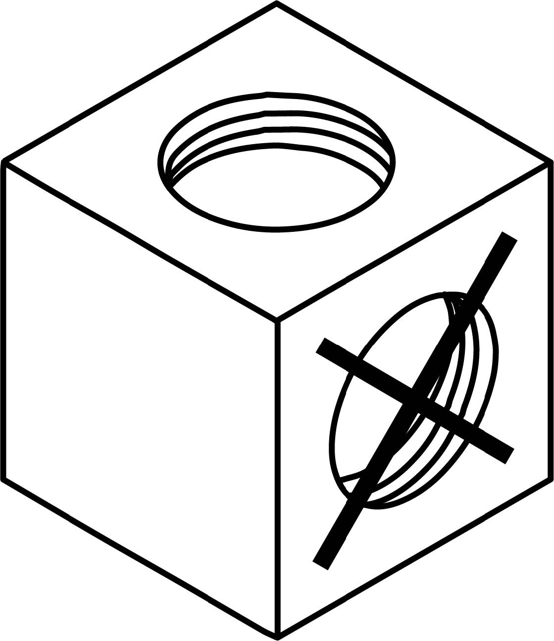
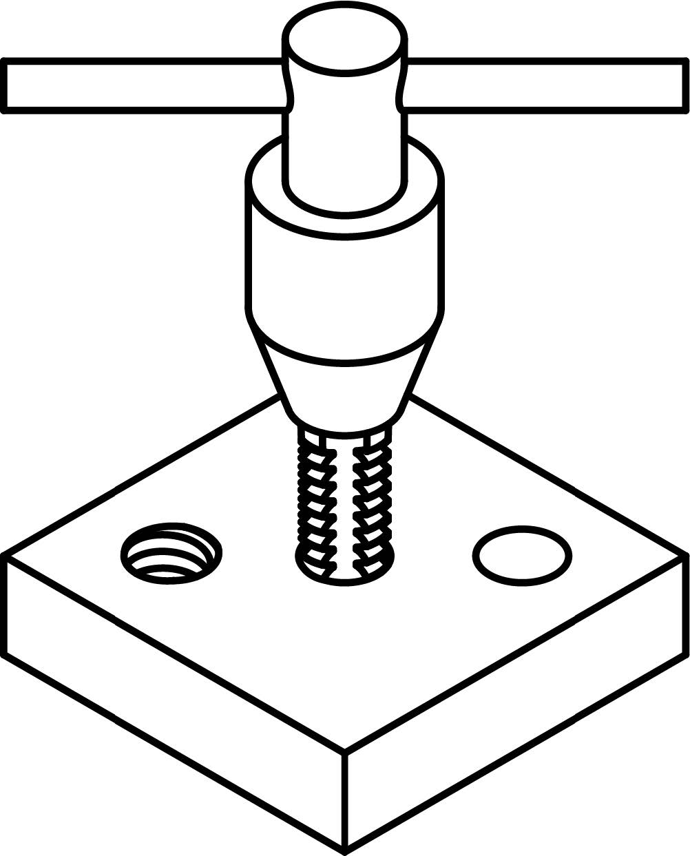
- Tapping & Threading: When designing parts for tapping, ensure hole dimensions are suitable for threading or include center marks for precise drilling of pre-tapped holes. Use a tap and drill chart to match the correct hole size with the desired thread. Keep in mind that tapping removes material and adds stress to the surrounding area, so reinforce fastener locations with sufficient wall thickness to prevent deformation or failure.
- Inserts: Inserts are not required for metal parts.
4.3 Other Factors
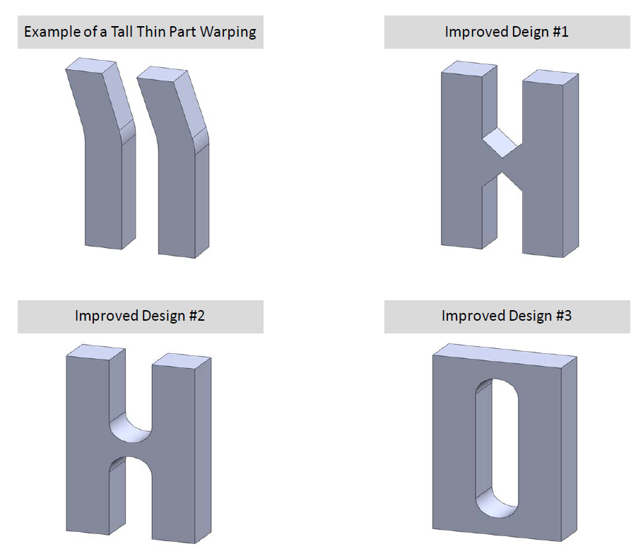
a. Part Strength During the Build During the build process parts are subjected to forces from spreading and compacting of new layers. Tall thin parts are susceptible to these lateral forces, causing inaccuracy in the parts’ features due to improper design or lack of support structures.
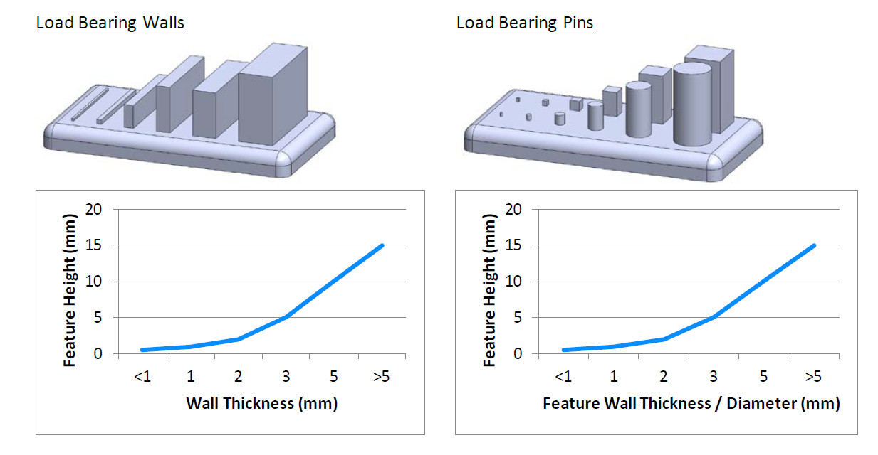
b. Load Bearing Features Load bearing part features require further guidelines for height to cross sectional ratios to ensure feature integrity. The figures below describe feature height to wall thickness ratios of load bearing walls and pins.
c. Distance Between Part Features During the DMLS process the laser creates a melt pool that is slightly wider than the laser diameter from heat dissipating into the surrounding powder. This will cause features that are close to each other to bond together or create a section of sintered powder that cannot be removed from between sintered areas in the part. Distance between features must maintain a distance of 0.4-0.5mm to adequately remove powder and allow for part movement.
d. Accuracy
- Positive features hold an accuracy of 20-150μm without any post processing. Negative features, such as holes smaller than 50mm, will typically be slightly undersized by 100-150μm.
- Surface finish will vary from material to material, however an unfinished part will have a surface finish of μm RA from 2-5.
e. How to Use this Information to Influence Your Designs:
- The quoted price of parts is heavily influenced by factors such as support structure design and removal of support factor. Therefore, minimizing the amount of support structure required will decrease design time, build time and post processing required. The best way to accomplish this is to make the geometry as self-supporting as possible.
- Try to Build Self Supporting Geometry:
Angles ≤ 30°
Utilize chamfers and fillets on corners and features
Implement features for weight and volume reduction
4.4 Cases for Example
EXAMPLE #1
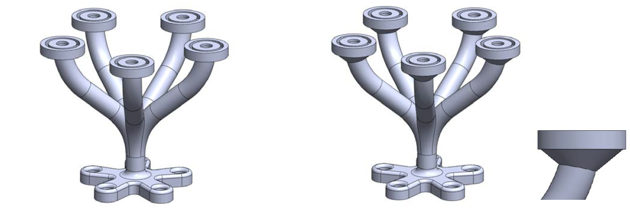
In this example the flanges towards the top of the part will cause a problem. The bottom facing surface of the flange will require some form of support. Adding a chamfer or a fillet to the overhanging geometry makes it self-supporting.
EXAMPLE #2
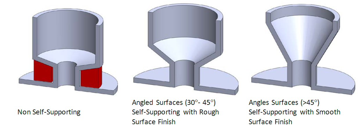
In this example the sloping angle of geometry is changed, making it self-supporting. Note that angles from 30°- 45° will self-support with some surface roughness and angles >45° will have a smoother surface finish.
EXAMPLE #3
The price of DMLS parts is heavily influenced by build time and the amount of material being used.
The surface area to volume ratio of a part plays a large role in determining the quoted price of a given part. A part with reduced mass allows for a lower price because it takes less time to build, uses less material, and has a higher success rate of being produced correctly the first time.
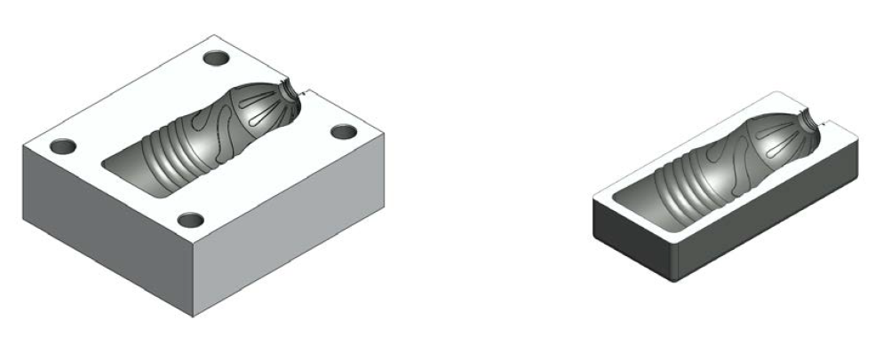
The volume of a part is decreased, either by redesign or by using another manufacturing process to create the geometry, the overall part price will go down significantly. In this example the important features of a mold are built using DMLS and the surrounding material is milled to save of overall assembly cost.
EXAMPLE #4
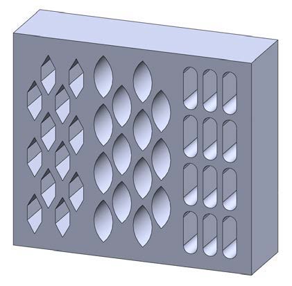
Reduce mass and volume by using self-supporting features in the vertical axis.
5. Material Selection for DMLS
Material selection is a crucial aspect of the DMLS process, as the material directly impacts the part’s performance, durability, and functionality. The choice of material must be made based on the specific requirements of the application, including strength, corrosion resistance, heat resistance, and weight. DMLS is compatible with a wide variety of metal powders, each offering unique properties suited for different applications.
5.1 Overview of Materials Suitable for DMLS
DMLS can utilize various metal powders that differ in their physical and mechanical properties. Some of the most commonly used materials in DMLS include:
- Stainless Steel: Stainless steel is one of the most popular materials for DMLS, particularly in industries like aerospace, automotive, and medical devices. Known for its strength, durability, and resistance to corrosion, stainless steel offers good fatigue resistance and can withstand high temperatures. It’s suitable for applications that require strength and resistance to environmental factors such as moisture and chemicals.
- Titanium Alloys: Titanium is a lightweight, corrosion-resistant material often used in aerospace, medical, and high-performance automotive applications. It is known for its excellent strength-to-weight ratio and resistance to heat and corrosion. Titanium alloys, such as Ti6Al4V, are frequently used in DMLS due to their ability to produce high-performance parts that need to withstand extreme conditions without adding significant weight.
- Cobalt Chrome: Cobalt chrome is known for its high strength, excellent wear resistance, and ability to withstand high temperatures. It is commonly used in medical devices (e.g., implants, dental components) and aerospace applications. Cobalt chrome is also biocompatible, making it ideal for producing parts in contact with the human body, such as surgical instruments and prosthetics.
- Inconel (Nickel-Based Alloys): Inconel is a family of high-performance alloys, particularly known for its resistance to oxidation and high-temperature stability. Inconel 625 and Inconel 718 are popular alloys for DMLS and are used in industries like aerospace, power generation, and chemical processing. These alloys excel in applications where parts must endure extreme heat and pressure.
- Aluminum Alloys: While not as commonly used as stainless steel or titanium, aluminum alloys are sometimes used for DMLS parts that require low weight and good mechanical properties. Aluminum is particularly useful in industries like automotive, where lightweight structures are essential, as well as in tooling and prototype applications.
- Tool Steels: Tool steels, such as H13 and A2, are used for producing molds, dies, and tooling parts in DMLS. These materials offer high wear resistance and toughness, making them ideal for creating high-stress components in manufacturing processes.
- Copper Alloys: Copper alloys are selected for their excellent electrical and thermal conductivity, making them ideal for applications in electronics, heat exchangers, and electrical components. DMLS of copper allows for the production of intricate parts with high thermal and electrical efficiency.
Below is a comparison table for your reference.
| Material | Key Parameters | Values/Properties | Key Notes |
| Stainless Steel (15-5PH/17-4PH) | High-Temperature Tensile Strength Ductility Creep Life Surface Roughness (Ra) Surface Hardness (Rv) Corrosion Resistance |
+30% -50% +30% (593°C/211 MPa) 5.04±0.56 μm -11.68±2.84 MPa Superior to cast |
Post-heat treatment improves density/strength; fine-grained structure enhances corrosion resistance |
| Titanium Alloy (Ti-6Al-4V) | Strength & Corrosion Resistance Defect Sensitivity Biocompatibility |
High fatigue strength Porosity-induced cracking risk Meets orthopedic/dental standards |
Requires optimized laser power/scan speed; preferred for aerospace & medical implants |
| Cobalt-Chromium Alloys (Co-Cr) | Tensile Strength Biocompatibility Surface Density |
~1200 MPa (brittle fracture) Hypoallergenic Dense, pore-free structure |
Ideal for surgical implants (e.g., joints, dental) |
| Nickel-Based Alloys (Inconel 718) | High-Temperature Stability Mechanical Performance |
Oxidation/corrosion resistance Outperforms cast parts |
Used in gas turbines, rocket engines |
| Aluminum Alloy (AlSi10Mg) | Corrosion Resistance Heat Treatment Impact Thermal Expansion Coefficient |
Superior to cast T6 reduces corrosion rate Low (ideal for DMLS) |
High-temperature annealing may degrade properties |
| Copper Alloy (CuNi2SiCr) | Tensile Strength Electrical/Thermal Conductivity Print Resolution |
Exceeds aluminum Exceeds aluminum Layer thickness: 20 μm |
Suitable for heat exchangers, electronic components |
| Tool Steel (H13/A2) | Wear Resistance Toughness |
High Good |
Requires experimental data; used for molds/tooling |
5.2 Considerations for Choosing the Right Material for Specific Applications
When selecting the most suitable material for a DMLS project, several factors must be considered:
- Mechanical Properties: Depending on the application, parts may need to withstand significant mechanical stress. Material properties such as tensile strength, yield strength, hardness, and fatigue resistance are critical in choosing the right material. For example, aerospace and automotive industries often require materials that can endure high-stress environments and maintain their strength under extreme conditions.
- Corrosion and Oxidation Resistance: For applications exposed to harsh environments or chemicals, materials with high corrosion resistance, like stainless steel or titanium, are essential. Industries like medical devices and marine applications place a high value on materials that can resist corrosion and maintain performance over time.
- Temperature Resistance: Certain industries, such as aerospace and power generation, require materials that can withstand high temperatures. Alloys like Inconel, titanium, and cobalt chrome are ideal for such applications due to their ability to maintain strength and resist oxidation in high-heat environments.
- Weight Requirements: Weight is a critical consideration in industries like aerospace and automotive, where minimizing mass is important for fuel efficiency and performance. Titanium and aluminum alloys are popular choices due to their lightweight nature while still providing strength and durability.
- Biocompatibility: For medical applications, selecting materials that are biocompatible and non-toxic is essential. Materials like titanium and cobalt chrome are commonly used in implants and surgical devices due to their biocompatibility, which ensures that they can be safely used in the human body.
- Post-Processing Needs: The material selected can influence the amount of post-processing required after the DMLS process. For example, some materials may require additional heat treatment, polishing, or surface finishing to meet the required specifications. Tool steels and stainless steels may require heat treatment to achieve desired hardness levels.
- Cost and Availability: Material costs can vary significantly depending on the type and complexity of the alloy. In some cases, cost-effective materials such as stainless steel might be sufficient for prototypes or lower-performance applications, while more expensive materials like titanium may be required for high-performance parts. Availability and supply chain factors should also be considered when selecting a material for mass production or long-term use.
6. Post-Processing Techniques in DMLS
Post-processing plays a significant role in the overall quality, performance, and appearance of parts produced through DMLS. While DMLS can create parts with complex geometries and precise details, post-processing is often required to refine the final product, enhance surface finish, improve mechanical properties, and ensure that the parts meet functional and aesthetic requirements.
6.1 Types of Post-Processing
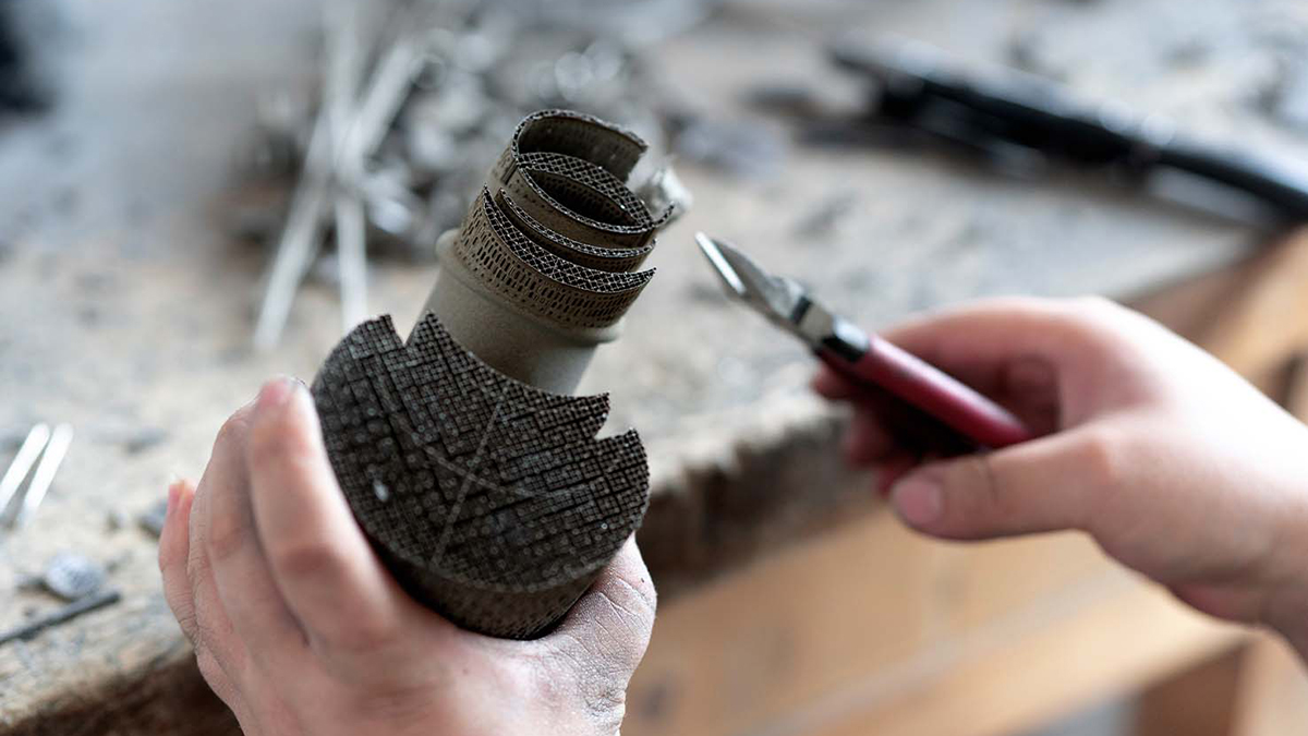
Post-processing techniques in DMLS are varied, depending on the desired final properties of the part and the material used. Common post-processing methods include:
- Removal of Support Structures: During the DMLS process, support structures are often required to ensure the part’s stability during sintering. These supports prevent warping or distortion as the metal powder fuses under the laser’s heat. After printing, these support structures must be carefully removed, typically using mechanical methods such as milling, grinding, or even manual hand tools. The complexity of support removal increases with the intricacy of the design, and this step requires precise handling to avoid damaging the part.
- Surface Finishing: Surface finishing techniques improve the surface quality of DMLS parts, eliminating the rough, powdery texture left by the sintering process. Common surface finishing methods include:
- Grinding and Polishing: These techniques are used to smooth out rough surfaces, improving both the visual appearance and the part’s function, especially in applications where surface texture is critical.
- Bead Blasting: This process involves blasting the surface with fine beads to provide a consistent, matte finish and improve the part’s overall texture.
- Electropolishing: This technique enhances the surface’s smoothness and corrosion resistance, particularly for metals like stainless steel. It involves using an electrochemical process to remove microscopic layers from the part’s surface.
- Heat Treatment: Heat treatment is often employed to enhance the mechanical properties of DMLS parts. Common treatments include:
- Annealing: This process involves heating the part to a specific temperature and then allowing it to cool slowly. Annealing helps relieve internal stresses, improves ductility, and reduces hardness, which is particularly useful for materials like stainless steel and aluminum.
- Hardening: For parts that need increased hardness and wear resistance, heat treatment processes such as quenching and tempering can be used. This is especially relevant for tool steels and parts used in high-stress applications.
- Solutionizing and Aging: This process is often applied to alloys like Inconel or titanium to enhance their strength and hardness. Solutionizing involves heating the part to a high temperature to dissolve certain elements, followed by aging, where the material is cooled to harden and stabilize the microstructure.
- Chemical Treatments: Chemical post-processing, such as passivation or plating, can be used to improve corrosion resistance. Passivation involves treating the part with an acid solution to remove contaminants and create a thin, protective oxide layer. Plating techniques like electroplating can also be applied to improve surface qualities, such as wear resistance or conductivity.
- Laser Treatment: Laser surface treatment involves using a high-powered laser to treat the surface of the part, improving its hardness, wear resistance, and sometimes its corrosion resistance. This technique is ideal for parts made of high-performance alloys, like Inconel, that need to withstand harsh conditions.
6.2 How Post-Processing Affects Part Quality and Performance
Post-processing has a profound impact on the final quality and performance of DMLS parts. The nature and extent of post-processing required depend on the material, the complexity of the part, and its intended use.
- Part Accuracy: Post-processing can enhance the dimensional accuracy of a part. Removal of support structures or any material left from the sintering process can help achieve tighter tolerances. Additionally, surface finishing can correct minor inaccuracies and improve the final appearance of the part.
- Surface Integrity: One of the primary reasons for surface finishing in DMLS is to improve the surface integrity of the part. As DMLS parts typically have a rough surface due to the sintering process, surface finishing methods such as polishing, grinding, and bead blasting significantly improve the smoothness and quality of the part’s surface. This is crucial for parts used in precision applications, such as medical devices or aerospace components, where smooth surfaces are critical for proper function, such as sealing or fitting.
- Mechanical Properties: Post-processing directly influences the mechanical properties of the part. Heat treatment, in particular, can significantly alter the hardness, strength, and fatigue resistance of the metal. For example, parts made from tool steels benefit from hardening processes, while titanium components may require annealing to optimize their strength and ductility.
- Durability and Wear Resistance: Post-processing can improve the wear resistance of DMLS parts. Techniques such as hardening or electroplating enhance the part’s ability to withstand friction, erosion, or corrosion, which is particularly beneficial for parts that will undergo extreme conditions, such as gears, cutting tools, or aerospace components.
- Functional Performance: Many DMLS parts are used in demanding applications, where the functionality of the part can be highly sensitive to its surface and mechanical properties. Post-processing ensures that the part meets the required specifications, whether it’s achieving a desired surface finish, ensuring dimensional accuracy, or improving its overall mechanical performance.
7. Challenges and Limitations of DMLS
While Direct Metal Laser Sintering (DMLS) offers significant advantages in terms of design flexibility, material options, and part complexity, there are also several challenges and limitations that manufacturers need to consider when deciding whether to use this technology. These challenges often relate to the cost, build size limitations, production scalability, and material properties, which can affect the suitability of DMLS for certain applications.
7.1 High Cost of DMLS
One of the most significant barriers to adopting DMLS is its high cost. Several factors contribute to the expense of using DMLS:
- Equipment Costs: The machines used for DMLS are expensive due to their advanced technology, precision, and the need for specialized lasers and material handling systems. The initial investment in DMLS machines is substantial, which may limit accessibility for small or medium-sized manufacturers.
- Material Costs: DMLS uses high-quality metal powders, which are often more expensive than traditional metal materials. Additionally, the need for high-purity powders, which are essential for achieving the desired part properties, further drives up material costs. The price of metal powders, such as titanium, cobalt-chrome, or stainless steel, can be prohibitively high, especially when considering the volume of material required for larger or more complex parts.
- Post-Processing: Post-processing steps, such as support removal, surface finishing, and heat treatment, also add to the overall cost of DMLS parts. These processes require time, labor, and additional equipment, further increasing the final cost of the produced parts.
- Energy Consumption: DMLS is an energy-intensive process, especially when working with high-performance materials like titanium or nickel alloys. The need for continuous high-energy laser sintering contributes to the operational costs.
7.2 Limited Build Size
While DMLS excels at creating complex geometries, the build size of parts is often limited by the size of the printer’s build chamber. This limitation poses challenges for manufacturing large parts or parts with significant volumes. The key aspects of this challenge include:
- Size Restrictions: The maximum build size of a DMLS machine is typically smaller than the maximum build size of traditional manufacturing methods like casting or machining. Most DMLS systems have a build volume that can accommodate parts measuring up to 300mm x 300mm x 300mm, although larger machines may have slightly bigger volumes. For parts larger than the maximum build size, the design must either be scaled down, split into multiple sections, or reengineered for assembly post-manufacturing.
- Part Assembly: For larger components, DMLS may require the production of individual subcomponents that are later assembled. This can introduce additional complexity in terms of design, part alignment, and post-processing steps. Additionally, the need for assembly can affect the overall strength and performance of the final part, as well as increase the cost and lead time for production.
- Material Waste: In some cases, to accommodate the limitations of build size, parts may need to be designed with additional supports, leading to a higher degree of material waste, which further increases the cost of production. Although metal powders can often be recycled, the extra material used for supports can be wasteful when parts are oversized or not optimized for the DMLS process.
7.3 Challenges in High-Volume Production
DMLS is an excellent choice for small to medium-sized production runs, but its scalability for high-volume production is limited by several factors:
- Slower Production Speeds: Compared to traditional manufacturing methods, such as injection molding or casting, DMLS typically involves slower production speeds. Each layer of the part is sintered individually by the laser, which can take time, especially for larger or more complex parts. As a result, DMLS may not be the best option for mass production of large quantities of identical parts, where speed and cost efficiency are critical.
- Batch Production: DMLS is generally suited for batch production rather than continuous, high-volume runs. The process of setting up the machine, loading materials, and completing post-processing steps can take time, limiting the overall throughput compared to other mass-production technologies. This makes it less suitable for applications where high volumes of identical parts are required in a short time frame.
- Cost Efficiency: For high-volume production, the costs of DMLS—particularly the costs of materials, machine time, and post-processing—can be prohibitive. Traditional manufacturing methods like injection molding or die casting often offer much lower per-unit costs for large quantities of parts, making them more economical for high-volume applications.
7.4 Material Limitations
While DMLS supports a wide range of metal materials, the selection is still limited compared to other traditional manufacturing methods. The available metal powders may not always meet the specific requirements of certain applications, especially when considering factors like material strength, durability, and thermal resistance. Some of the challenges related to material limitations include:
- Limited Powder Options: While DMLS works well with materials such as stainless steel, titanium, cobalt-chrome, and Inconel, other materials, such as certain aluminum alloys or low-cost steels, may not yet be as compatible with the technology. Additionally, the material properties of some powders can be less predictable, especially when dealing with alloys that require precise control over their microstructure.
- Material Properties: DMLS materials can exhibit slightly different mechanical properties compared to traditionally manufactured metals due to the nature of the sintering process. For example, parts produced through DMLS may experience anisotropic properties, meaning that their strength and performance vary depending on the build orientation. This can affect the overall reliability and function of the part, particularly for critical applications that require consistent performance in all directions.
7.5 Surface Finish and Resolution
While DMLS is capable of creating parts with impressive detail, the surface finish may not always meet the required specifications without additional post-processing. As mentioned earlier, parts produced with DMLS often have a rough surface texture, which may not be acceptable for certain applications without further refinement. The resolution of the laser can also pose limitations in achieving ultra-fine details, particularly in highly intricate geometries, where post-processing becomes necessary.
8. Cost Considerations in DMLS
Direct Metal Laser Sintering (DMLS) offers a range of benefits, but it’s essential to understand the factors that influence the overall cost of producing parts. Several elements contribute to the final price, from the complexity of the design to the material choices and build time. By understanding these factors and optimizing designs, companies can reduce costs without compromising the performance of the parts.
8.1 Factors Influencing the Cost of DMLS Parts
a. Build Time:
One of the primary factors that impacts cost is the time it takes to build the part. The longer the build time, the higher the overall cost. DMLS works by layering metal powder and sintering it with a laser, and the process can take hours or even days depending on the complexity and size of the part. Reducing part size, optimizing layer thickness, and minimizing unnecessary features can help shorten build time, thus reducing costs.
b. Material Usage:
The type and amount of material used in the production process also play a significant role in the cost. Expensive metals such as titanium or cobalt chrome, for example, will naturally increase the cost of the part. Additionally, the amount of unused powder that cannot be recycled after the build process contributes to material waste, which affects the overall cost. Choosing materials that strike a balance between cost and performance, and optimizing the design to minimize material waste, can lower costs.
c. Complexity of the Design:
Parts with complex geometries, intricate features, and high precision requirements are more costly to produce with DMLS. Intricate details can result in longer print times, more support structures, and additional post-processing steps. Simple designs with fewer features generally incur lower costs, but it’s essential to ensure that the part still meets functional requirements.
d. Post-Processing Requirements:
DMLS parts often require post-processing to remove support structures, smooth surfaces, or enhance mechanical properties through heat treatment. The complexity of post-processing affects the total cost of the part. Parts with fewer supports, simpler surfaces, and less need for heat treatment will reduce the overall cost.
8.2 How to Optimize Part Design to Reduce Costs
a. Design for Manufacturability (DFM):
One of the most effective ways to reduce DMLS costs is to design parts that are optimized for the additive manufacturing process. This includes reducing the need for support structures by designing self-supporting geometries and avoiding overhangs. Simple and efficient designs can significantly reduce build time and post-processing, directly impacting costs.
b. Minimize Material Usage:
To cut costs, consider minimizing material usage by using lattice structures or hollow sections where possible. These methods can significantly reduce the weight and material needed without compromising part strength. Parts can be designed with internal geometries that optimize material usage while maintaining the required mechanical properties.
c. Reduce Part Size and Complexity:
A smaller part with fewer features will generally take less time to print and use less material. However, ensure that any design reduction does not compromise the functionality or performance of the part. Simpler geometries with less intricate detailing are faster and cheaper to produce.
d. Optimize Build Orientation:
The orientation of the part on the build platform can influence both the material usage and the build time. By optimizing the build orientation, designers can reduce the number of supports required and minimize the time spent on the printing process. Strategic orientation can also enhance the quality of the part, reducing the need for extensive post-processing.
e. Material Recycling:
Another method for reducing DMLS costs is to ensure that unused powder can be recycled. Many metal powders used in DMLS can be reused in subsequent builds, reducing the overall material cost. This practice helps maximize material usage and minimize waste.
By addressing these cost drivers early in the design process, manufacturers can achieve significant savings, making DMLS a more cost-effective solution for metal part production.
Conclusion
In summary, Direct Metal Laser Sintering (DMLS) is a transformative technology for metal part production, offering significant advantages in terms of design flexibility, speed, and material variety. The ability to create complex geometries and reduce part count makes it a preferred choice for industries ranging from aerospace to healthcare. While there are considerations related to cost, material usage, and post-processing, these can be mitigated through thoughtful design and process optimization.
As a top on-demand production service provider, KingStar excels in utilizing DMLS technology to deliver high-quality, precision metal parts for a wide range of applications. With our expertise in both the technical and material aspects of DMLS, we ensure that our clients benefit from the full potential of this advanced manufacturing method, providing cost-effective solutions without compromising on quality. Whether you’re designing for aerospace, automotive, or medical applications, send email to sales@kingstarmold.com or leave online message, and we are committed to producing superior parts that meet your specific needs.
