With the intensification of market competition, more and more enterprises realize the importance of shortening product development time. Improving the speed of product development is of great significance for enterprises to respond quickly to customer needs, improve the competitiveness of enterprises, and reduce the cost of product development. The “design for manufacturing”, or, DFM is such an effective design method that fully considers the requirements of manufacturing in the design stage, reduces the number of design modifications, and “do things right the first time”, and thereby shortening the product development cycle and reducing product development costs.
- What is DFM?
- What’s the development mode of DFM?
- Benefits of Applying Design for Manufacturing (DFM) Principles
- DFM Principles for Injection Molded Plastic Products
- Practical DFM skills in actual design
- 19 key points about injection mold DFM production process
- DFM in the Plastic Injection Molding Process
- Advantages of Incorporating DFM EARLY in the Design Process
- 1. Cost Efficiency Through Fewer Iterations and Reduced Waste
- 2. Time Savings from Streamlined Processes
- 3. Enhanced Product Performance and Durability
- 4. Improved Collaboration Between Design and Manufacturing Teams
- 5. Reduced Risk of Design Errors and Manufacturing Defects
- 6. Easier Identification of Potential Design or Manufacturing Issues
- 7. Better Alignment with Customer Expectations and Requirements
- 8. Streamlined Production Processes for Faster Time-to-Market
- Tools and Techniques for Effective DFM
- Common Challenges in DFM for Plastic Products
- Conclusion
What is DFM?
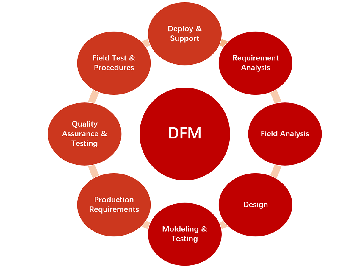
DFM, Design for Manufacturing, or, design for manufacturability, is a design approach for parallel engineering. The main idea is to consider the constraints of manufacturing factors in the early design stage of the product (for example, the machine tool equipment required for product manufacturing, processing tools, measuring tools and the corresponding time, cost, etc.), and provide it to the designer in a timely manner, as the basis for design and modification of the program.
In all stages of product design, under the premise of ensuring product function, manufacturability should be fully considered, and the development time, cost and quality of the product should be controlled within the expected range.
What’s the development mode of DFM?
In the traditional serial engineering product development model, product design and process design are two independent and sequential processes, as shown in Figure 1a below.

1a
This mode is easy to cause the product design process and manufacturing process disjointed, making the product manufacturability, assemblability and maintainability poor, resulting in difficult design changes, long product development cycle, high cost. And the quality is difficult to guarantee, and even a large number of designs can not be put into production, resulting in a huge waste of manpower and material resources.
The concept of DFM challenges the traditional product development model, breaking the order of traditional design methods and developing product design and process design in parallel, as shown in Figure 1b.

1b
DFM fully considers a variety of manufacturing constraints, processing conditions, clamping schemes, tooling design and parts standardization, etc., to review and decide on the design of the scheme, and to feedback the review results to the designer in time, who then put forward suggestions for modification and guidance for product design. This is a simpler and more effective new product development method, which provides a feasible way for enterprises to reduce production costs, shorten product development cycle and improve enterprise benefits.
Benefits of Applying Design for Manufacturing (DFM) Principles
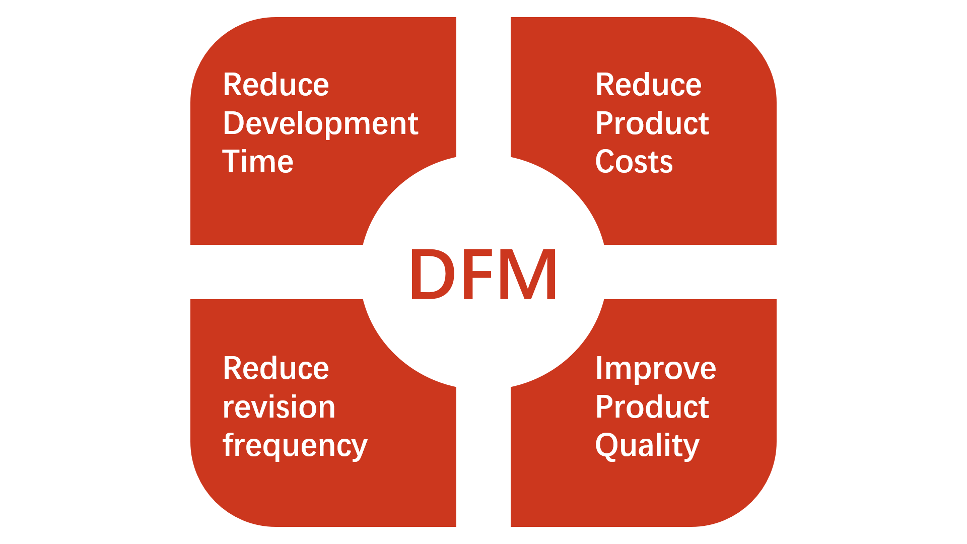
Incorporating DFM principles in the design of plastic products offers transformative advantages across various aspects of manufacturing. These include:
1. Cost Efficiency
- Reduced Material Waste: Optimized designs minimize excess material usage.
- Lower Tooling Costs: Simplified designs lead to less complex molds and tooling, reducing production expenses.
- Fewer Design Iterations: Addressing potential manufacturing issues early cuts down on costly rework and redesign efforts.
2. Accelerated Production
- Streamlined Manufacturing: Well-thought-out designs reduce process complexity, speeding up production cycles.
- Faster Time-to-Market: By resolving manufacturability issues upfront, production starts earlier, shortening overall project timelines.
- Efficient Tooling and Setup: Optimized molds and reduced adjustments allow for smoother production runs.
3. Enhanced Product Quality
- Consistency in Production: Designs that account for manufacturing tolerances ensure higher repeatability and fewer defects.
- Durability and Performance: DFM helps identify and mitigate potential weak points, resulting in products that meet or exceed quality expectations.
- Reduced Post-Processing: Fewer finishing steps are required when designs align with manufacturing capabilities.
4. Operational Advantages
- Better Collaboration: DFM encourages teamwork between design, engineering, and manufacturing teams, leading to more cohesive projects.
- Customer Satisfaction: High-quality, cost-effective products delivered on time boost customer trust and loyalty.
- Sustainability: Efficient designs reduce waste and energy use, contributing to eco-friendly manufacturing practices.
DFM Principles for Injection Molded Plastic Products
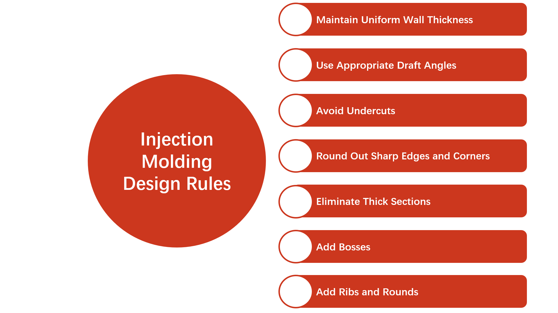
1. Material Selection
- Choose the Right Material: Select materials based on the product’s functional requirements (strength, flexibility, heat resistance, etc.). Ensure the material is suitable for injection molding and compatible with the mold design.
- Consider Material Flow: Different plastics have varying flow properties. Choose materials that can easily fill the mold without defects like air pockets or weld lines.
2. Wall Thickness Optimization
- Uniform Wall Thickness: Avoid areas with varying wall thickness, as they can lead to warping, uneven cooling, and sink marks. Design parts with consistent wall thickness to ensure uniform flow and cooling.
- Thicker Walls: If thicker walls are necessary, consider using ribs or gussets to maintain structural strength without overloading the part.
| Material | Recommended Wall Thickness |
|---|---|
| ABS | 0.045-0.140 |
| Acetal | 0.030-0.120 |
| Long-Fiber Reinforced Plastic | 0.075-1.000 |
| Nylon | 0.030-0.115 |
| Polyethylene | 0.030-0.200 |
| Polypropylene | 0.025-0.150 |
| Polystyrene | 0.035-0.150 |
| Polyurethane | 0.080-0.750 |
| Rigid PVC | 0.090-0.250 |
| Soft PVC | 0.025-0.150 |
3. Mold Design Considerations
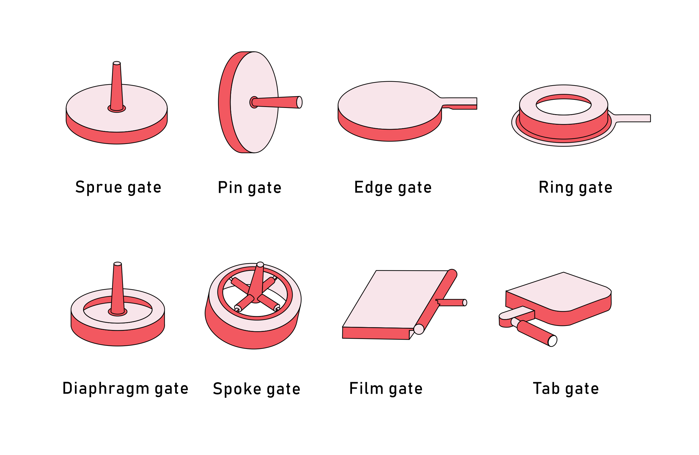
- Proper Gate Placement: Gate location impacts how the plastic fills the mold. Position gates where the flow is uniform to avoid weld lines and air traps. Place gates away from high-stress zones to prevent defects; Fill thicker sections first; Distribute material evenly with multiple gates in the runner system; Hide gate marks in the part design to minimize their impact.

- Draft Angles: Incorporate draft angles (typically 1–3 degrees) on vertical surfaces to facilitate easy ejection from the mold, reducing wear and tear on the mold and improving cycle times.
- Parting Lines: Avoid placing parting lines on visible or functional surfaces to enhance the product’s aesthetic and structural integrity.
- Bosses: Add a base radius (25-50% of wall thickness); Link to an external wall via a rib; Keep rib height under 3X outer diameter; Space multiple bosses at least twice adjacent wall thickness.
- Corners: Internal corners should be ≥ 50% of adjacent wall thickness; External corners need 150% of adjacent wall thickness; Boss radius = 25% adjacent wall, min 0.381mm (0.015 inches).
4. Minimize Complex Geometries
- Simplified Design: Avoid overly complex shapes and geometries that could increase mold complexity and production time. Use simple, uniform features to streamline manufacturing and reduce costs.
- Avoid Undercuts: Undercuts complicate mold design and require specialized tooling. Instead, design parts with features that can be molded without additional complex tooling.
5. Tolerances and Fit
- Realistic Tolerances: Set realistic tolerances that balance manufacturability and function. Tight tolerances can increase mold complexity and cost, while looser tolerances may affect product performance.
- Allowances for Shrinkage: Account for the material’s shrinkage during cooling. Proper allowances for this can prevent warping or dimensional issues in the final product.
6. Ribs and Supports
- Use Ribs for Strength: Design with ribs instead of thick sections to provide strength without increasing wall thickness. Ribs should be tapered and have rounded corners to reduce stress concentrations. And in actual design, make base thickness ≤ 2/3 adjoining wall thickness, and rib height ≤ 2.5 times nominal wall thickness.
- Avoid Over-engineering: Keep ribs and supports simple and efficient—avoid unnecessary additions that could complicate the mold or affect part quality.
7. Ejection System Design
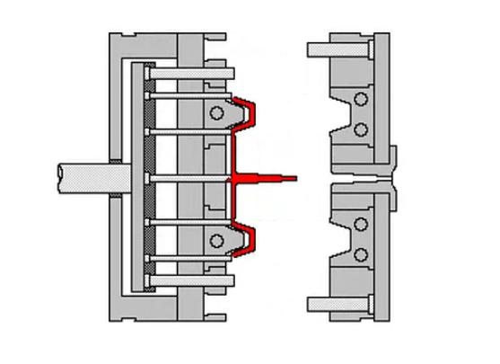
- Ejector Pin Placement: Plan the placement of ejector pins to avoid damaging the part and ensure smooth ejection. Proper placement reduces wear on both the mold and the parts.
- Ejection Marks: If ejector pin marks are inevitable, design them to be placed in non-visible or non-functional areas to minimize their impact on the product’s appearance.
8. Ventilation and Cooling Systems
- Proper Venting: Ensure that the mold has sufficient vents to allow air to escape as the material fills the cavity. This prevents air pockets, burns, and incomplete filling.
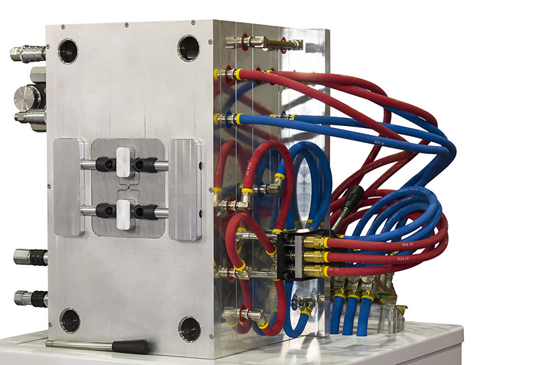
- Optimized Cooling Channels: Design efficient cooling systems within the mold to ensure even cooling and reduce cycle times. Proper cooling helps minimize warping and improves production consistency.
9. Assembly Considerations
- Design for Assembly: If the plastic part is part of a larger assembly, consider ease of assembly when designing the part. Use snap-fits or interlocking features that reduce the need for additional fasteners or secondary operations.
- Ease of Handling: Ensure the design allows for easy handling and placement during assembly processes, reducing labor time and costs.
Practical DFM skills in actual design
⑴ Minimize the number of parts to simplify the design (following the KISS principle: Keep It Simple, Stupid).
(2) Use CAE (Computer-Aided Engineering) software during the DVT (Design Validation Testing) stage to refine and validate the design.
(3) Apply modular design principles, aiming to create standardized, interchangeable modules.
(4) Avoid over-design to minimize unnecessary costs.
(5) Prioritize the use of readily available standard parts and raw materials.
(6) Ensure the overall design accommodates the assembly process, techniques, and workflows. Collaborate with the production team if needed.
(7) Adjust tolerances to focus on critical components, balancing functionality with manufacturability.
(8) Follow the design checklist rigorously to ensure all requirements are met.
19 key points about injection mold DFM production process
| Category | Key Points Description and Suggestions |
|---|---|
| Mold Version | Initial release or update, including revision records. |
| Drawing Information | Customer’s 3D and 2D drawings with version numbers, names, and major revisions. |
| Plastic Materials | Material suppliers, form, color, shrinkage rate, and moisture content requirements. |
| Injection Machine | Consider part size, mold size, shot weight, material properties, screw requirements, automation system, production rate, and critical factors such as clamping force and injection pressure. |
| Model Analysis | External dimensions (length, width, height), wall thickness uniformity, and local complex geometry. |
| Surface Finish | Confirm 2D surface finish requirements, SPI/VDI standards, and special surface treatments (Polish, EDM, etching, sandblasting, coating); ensure Ra value compliance. |
| Draft Angle | Ensure appropriate draft angle based on material type and surface texture to avoid sticking or difficulty during mold ejection. Refer to VDI guidelines. |
| Parting Line / Surface | Define cavity/core interface, parting lines for slides, and ensure parting lines are located to minimize impact on aesthetics and functionality. Simplify mold design for ease of manufacture. |
| Gate Design | Specify the location, size, and type of gate (e.g., edge, tunnel, hot runner gate) including cross-sectional view and dimensions. |
| Slider Design | Define sliders and their corresponding parting lines. |
| Ejector Pin Design | Describe the location, size, and type of ejector pins (including parting line) to ensure efficient ejection without damage to the part; Specify venting locations on the core and cavity, sliders, and ejector pins; Ensure vents are sized appropriately to avoid molding defects. |
| Insert Design | For complex molds, inserts (such as for cooling or localized features) may be used to facilitate machining, ease maintenance, and enable design modifications. Inserts may affect mold strength. |
| Mold Layout | Define the mold structure, layout of components such as cavities, cores, runners, ejector pins, and the use of cold or hot runner systems. Specify mold base, plate material, and part numbers. |
| Temperature Control System | Detail the cooling and heating system, including water flow (inlet/outlet locations), number of channels, manifold details, and temperature control system design. |
| Exhaust System | Descriptions of venting locations and dimensions for both the core and cavity, sliders, and top pins; adjustments made based on trial molding. |
| Part Ejection System | Define the method of part removal: manual, automated with fixtures, or robotic system. Include dimensions for robotic grippers and force distribution for safe and efficient ejection. |
| Concerns & Solutions | Identify any manufacturability issues discovered during the design review phase. Propose modifications to improve structural integrity and manufacturing ease (e.g., R-chamfers, sink marks). |
| Residence Time | Document injection molding cycle time, material density, shot weight, and flow rate; calculate filling, cooling, and packing time. |
| Mold Flow Analysis | Use Moldflow or other simulation software to analyze mold filling, cooling, and packing stages. Identify potential defects (e.g., air traps, weld lines) and optimize process parameters. |
DFM in the Plastic Injection Molding Process
1. Role of DFM in Mold Creation, Cycle Time Optimization, and Defect Reduction
a. Mold Creation:
DFM principles guide the design of molds to ensure manufacturability while reducing complexity and costs. By addressing factors like draft angles, parting lines, and gating systems early, mold designs can be optimized to:
- Enhance mold longevity.
- Simplify production processes.
- Minimize machining challenges and errors.
b. Cycle Time Optimization:
Thoughtful DFM considerations, such as uniform wall thickness, proper cooling system design, and balanced runner systems, help:
- Reduce cooling and filling time.
- Improve overall production speed.
- Maintain consistent quality, even in high-volume production.
c. Defect Reduction:
DFM reduces defects like warping, sink marks, air traps, and weld lines by:
- Improving material flow with effective mold designs.
- Ensuring proper venting and ejection mechanisms.
- Simulating mold flow (e.g., using Moldflow software) to anticipate potential issues.
2. Examples of DFM Impacting Injection Molding Efficiency
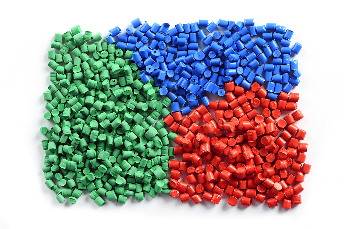
a. Material Selection:
For a high-strength, lightweight part, choosing a material with appropriate shrinkage rates and compatibility with mold design reduces post-processing and defects.
b. Gate Design Optimization:
A product requiring uniform filling benefits from a hot runner system, ensuring consistent material flow and reducing scrap rate.
c. Cooling System Efficiency:
Optimizing water channel placement reduces cycle times significantly in large molds, leading to higher production efficiency.
d. Part Simplification:
Redesigning a product to eliminate undercuts reduces the need for complex slides or lifters in the mold, simplifying manufacturing and reducing costs.
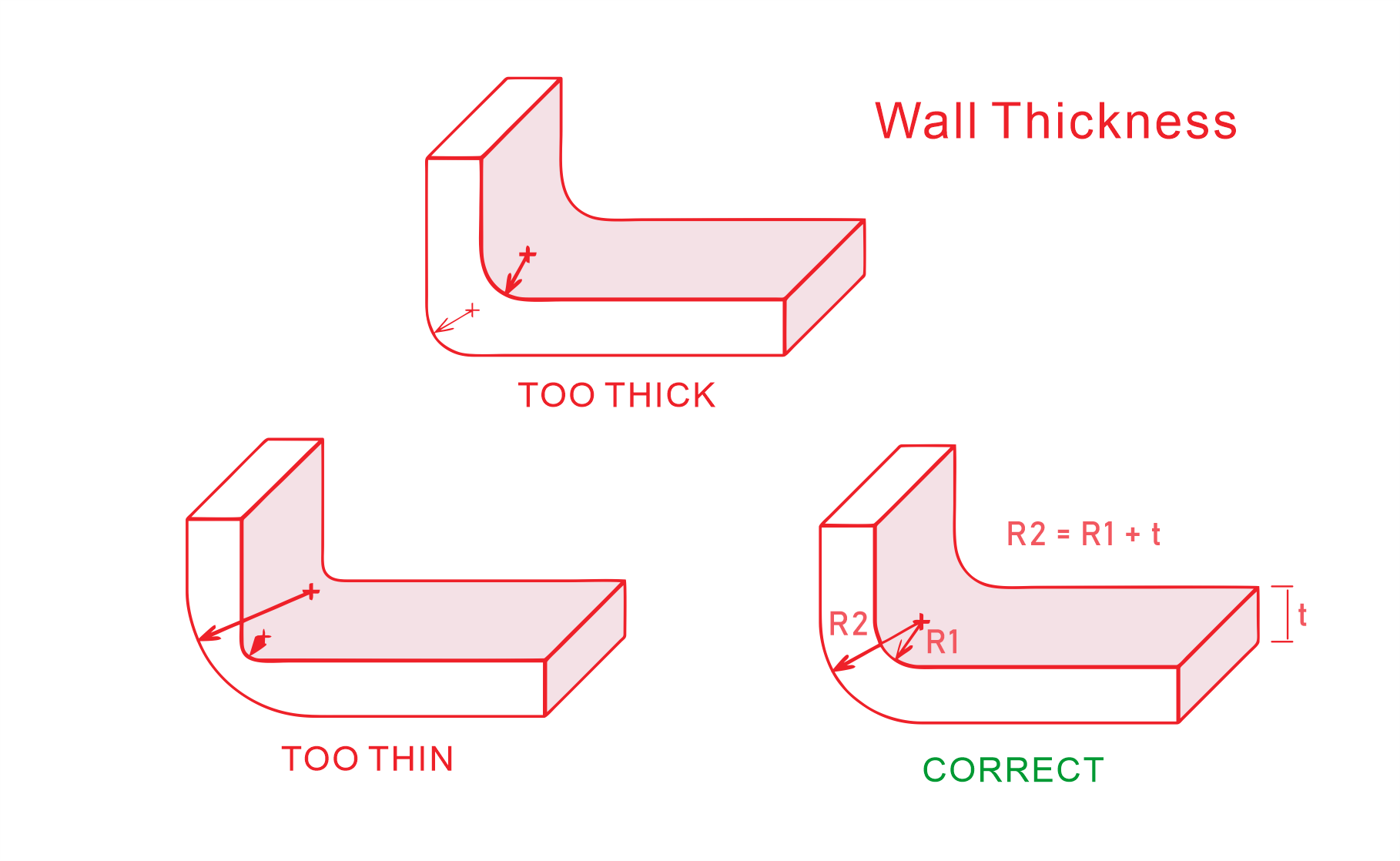
e. Wall Thickness Control:
Maintaining consistent wall thickness across the part minimizes warping, reduces material usage, and shortens cooling times.
Advantages of Incorporating DFM EARLY in the Design Process
Incorporating Design for Manufacturing (DFM) principles early in the product design process has become an essential practice for companies seeking to optimize their design-to-production workflows. DFM is a proactive approach that focuses on designing products in a way that makes them easier, more cost-effective, and quicker to manufacture. By integrating DFM from the beginning, businesses can unlock a range of benefits that enhance overall efficiency and product quality. Below, we explore the key advantages of incorporating DFM early in the design phase.
1. Cost Efficiency Through Fewer Iterations and Reduced Waste
One of the most significant advantages of incorporating DFM early is cost efficiency. DFM helps identify potential manufacturing challenges early on, which can prevent the need for costly design revisions later in the process. By considering the manufacturability of a product during the design phase, companies can optimize designs to minimize waste and reduce the number of iterations required. This not only leads to lower production costs but also reduces material wastage and the need for expensive changes during the prototyping or production stages.
2. Time Savings from Streamlined Processes
DFM significantly shortens product development cycles by streamlining processes. When manufacturers and designers collaborate early on, they can identify design issues and manufacturing constraints before they become roadblocks. This reduces the likelihood of delays due to design rework or production difficulties. By addressing these challenges in the design phase, companies can move forward more efficiently and reduce time-to-market, giving them a competitive edge in rapidly evolving industries.
3. Enhanced Product Performance and Durability
Integrating DFM early in the design process also contributes to improved product performance and durability. By considering factors such as material selection, manufacturing methods, and assembly processes, DFM ensures that products are designed to withstand real-world use while maintaining functionality. This approach allows designers to identify potential weaknesses in the product’s design and refine them before production begins, ensuring that the final product meets or exceeds customer expectations in terms of performance and longevity.
4. Improved Collaboration Between Design and Manufacturing Teams
When DFM principles are implemented early, design and manufacturing teams work more closely together. This fosters better communication and a shared understanding of the challenges each team faces. Designers are more aware of manufacturing constraints and capabilities, while manufacturers can provide valuable insights into potential design improvements based on their expertise. This collaborative environment leads to more informed decision-making and results in designs that are optimized for both functionality and manufacturability.
5. Reduced Risk of Design Errors and Manufacturing Defects
DFM allows teams to identify potential design flaws and manufacturing issues before they escalate into costly errors or defects. By considering how the design will be produced, assembly challenges, and the potential for manufacturing defects, DFM enables designers to create more robust products. Early identification of potential problems helps to ensure that products are manufactured according to specifications, with fewer defects and rework required during production.
6. Easier Identification of Potential Design or Manufacturing Issues
Another benefit of DFM is the ability to pinpoint potential issues at an early stage, when they are easier and cheaper to address. By simulating manufacturing processes or collaborating with experts during the design phase, companies can foresee challenges such as assembly difficulties, material limitations, or tooling constraints. Identifying and addressing these issues early prevents delays, reduces production costs, and ensures smoother production workflows.
7. Better Alignment with Customer Expectations and Requirements
DFM also plays a critical role in aligning product designs with customer requirements. By incorporating manufacturability considerations early in the process, companies can ensure that their designs are not only feasible to produce but also meet the functional and quality expectations of the end user. This helps avoid costly revisions and ensures that the product is delivered to market in line with customer demands, improving customer satisfaction and fostering stronger brand loyalty.
8. Streamlined Production Processes for Faster Time-to-Market
Lastly, implementing DFM early leads to smoother production processes, allowing companies to ramp up manufacturing quickly. Because the product is already designed with ease of production in mind, there are fewer unexpected challenges during production. This efficiency enables faster time-to-market, allowing businesses to respond more quickly to changing market conditions and capitalize on new opportunities.
Tools and Techniques for Effective DFM
| Category | Tools/Methods | Key Benefits |
|---|---|---|
| CAD Software | SolidWorks, AutoCAD, Creo | Precise modeling of complex geometries. |
| CATIA, NX | Automated checks for design issues. | |
| Fusion 360 | Integrates material properties and mold data. | |
| Simulation Tools | Moldflow, SolidWorks Plastics | Identifies air traps, weld lines, shrinkage. |
| ANSYS, Simulia | Optimizes gate, runner, and cooling systems. | |
| Prototyping Methods | Rapid Prototyping: 3D printing | Quick and cost-effective design validation. |
| CNC Machining | Accurate prototypes with production material. | |
| Collaboration | Design reviews with engineers | Aligns aesthetics with manufacturability. |
| Shared CAD/simulation results | Reduces costly late-stage changes. | |
| Cross-functional workshops | Improves design and production outcomes. |
Common Challenges in DFM for Plastic Products
While Design for Manufacturing (DFM) offers significant advantages, it also comes with its own set of challenges, particularly in the context of plastic products. These challenges must be carefully addressed to achieve a balance between manufacturability, functionality, and cost-effectiveness. Below are some common challenges faced when implementing DFM for plastic products:
1. Material Limitations
One of the key challenges in DFM for plastic products is balancing material properties such as strength, flexibility, and cost. High-strength materials often come with a premium price tag, making them less feasible for budget-conscious projects. On the other hand, using lower-cost materials might compromise the durability or performance of the product. Additionally, certain resins have limitations when it comes to color options, surface finishes, or the ability to meet specific performance standards. These material constraints can make it challenging to meet both design and manufacturing requirements while keeping costs in check.
2. Aesthetics vs. Manufacturability
Another significant challenge in DFM is balancing aesthetic requirements with the practicalities of manufacturing. Complex design elements such as undercuts, intricate textures, and fine details can complicate the molding process, increasing mold complexity and manufacturing costs. For instance, transparent plastic parts often require high-polish molds to achieve the desired clarity and appearance, which can increase production costs by up to 25%. Furthermore, high-polish finishes may introduce challenges in maintaining defect-free parts, as such finishes are more susceptible to imperfections and defects during molding. This also tends to increase cycle times, further escalating production costs. Achieving the right balance between aesthetics and manufacturability is crucial for maintaining both design appeal and cost-effectiveness.
3. Customer Expectations
Customers often demand products with premium aesthetics and high functionality at competitive or low costs, which can create unrealistic expectations. They may expect intricate designs, exceptional performance, and perfect finishes within tight timelines and budgets. However, these expectations often conflict with the practicalities of manufacturing. Unrealistic deadlines or budgets can force compromises in design, material choice, or production methods, potentially affecting product quality and manufacturability. It’s essential for both the design and manufacturing teams to manage customer expectations effectively, ensuring that their needs are met within feasible and cost-efficient parameters.
By recognizing and addressing these common challenges early in the design process, companies can better navigate the complexities of DFM for plastic products, ensuring a smoother, more cost-effective production journey.
Conclusion
At KingStar Mold, we specialize in Design for Manufacturing (DFM) to optimize plastic product designs for efficiency, quality, and cost-effectiveness. Whether you need consulting, mold design, or full-scale manufacturing, our team is ready to assist.
