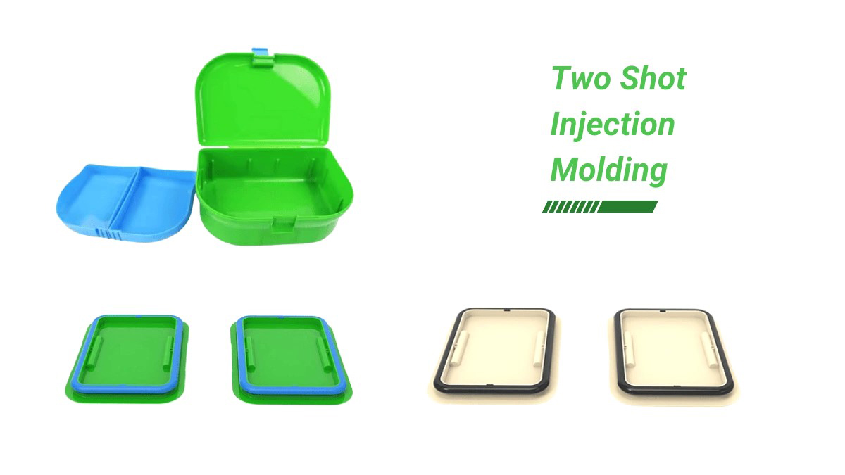
In modern manufacturing, with the increasing demand for product appearance, texture, and functional diversity in the consumer market, two-shot injection molding technology has gradually become one of the core processes for high-end product production due to its advantage of achieving “multi-color/multi-material integration in a single molding cycle”.
As a leading injection molding company, today we will comprehensively introduce two-shot injection molding technology, from its origin, principles to mold design, to give you a thorough understanding!
1. Origins and Industry Background of Two-shot Injection Molding
The new technology of two-shot injection molding originated from Arburg company, which began developing multi-color injection molding machines in 1961 with the goal of fully improving the production efficiency of two-shot parts. At that time, the main method was the technique of insert overmolding.
From the perspective of industry development, two shot injection molding, as an important branch of multi-component injection molding, can significantly enhance the design freedom and functional integration of products compared to traditional single component injection molding. For example, it can achieve a combination of “soft rubber anti slip+hard rubber load-bearing” and a multi-color gradient aesthetic effect. Therefore, it has become a research and application hotspot in the global injection molding industry.
This new technology is currently a hot topic in research and application in China, which is significantly different from single component injection molding. However, due to the high cost of imported equipment, complex injection molding processes and mold structures, the two-color injection molding process has not been widely introduced and applied in China. Generally, dual component or dual color products are produced through alternative processes.
Additional explanation: According to industry test data, there is a clear priority for the impact of process parameters on the quality of two-shot injection molded products.
- For Volume Shrinkage Rate: Melt Temperature>Holding Pressure, Injection Speed>Mold Temperature;
- For Sink Mark Index: Holding Pressure>Melt Temperature>Injection Speed>Mold Temperature.
Mastering this law can significantly reduce the cost of process debugging.

2. Process Definition and Molding Principle of Two-shot Injection Molding
2.1 What is Two-shot Injection Molding Process?
The so-called two-shot injection molding is a molding method that uses injection machines with two or more injection systems to simultaneously or sequentially inject different types and colors of plastics into molds. According to the mold structure and molding effect, it can be mainly divided into three categories: clear shot injection molding with two shot multi-mode, clear shot injection molding with two shot single-mode, and mixed shot injection molding with two shot single-mode.
The core difference from ordinary injection machines is that two-shot injection molding machines are equipped with two independent injection systems (which can respectively transport different materials/shots of melt), and must also have a mold rotation mechanism – either a rotary platen structure that drives the dynamic mold to rotate (multi-mode solution), or a rotary cavity structure that drives the mold cavity to rotate (single-mode solution), which is the key to achieving “two/multi-color parts in one cycle”.
2.2 Core Principles of Two-shot Injection Molding
A two-shot mold usually consists of two sets of molds: one half is installed on the fixed mold plate of the two-shot mold injection molding machine (i.e. the side with injection gates), and the other half is installed on the rotating mold plate (i.e. the side with the ejection system). The core design point is that the dynamic molds of the two sets of molds are usually completely identical, while there are differences between the first fixed mold (for the first material) and the second fixed mold (for the second material).
Complete Molding Cycle Process:
1) First Injection Molding: The first injection system injects the first material into the mold cavity to form the “first-shot part” (substrate);
2) Mold Rotation: The fixed and moving molds are opened under the force of the injection molding machine, and the rotary platen of the moving mold rotates 180° with the product (at this time, the part is not ejected to avoid damaging the product);
3) Second Injection Molding: The mold closes again, and the second injection system injects the second material into the reserved cavity, wrapping/bonding it on the surface of the first-shot part to form the “second-shot part” (finished product);
4) Finished Product Ejection: After insulation and cooling, the fixed and moving molds open again, and the second-shot part on the moving mold side is ejected.
Key Features: Each molding cycle simultaneously produces one set of first-shot parts and one set of finished products, ensuring efficiency and continuity.
2.3 Schematic Diagram of Two-shot Injection Molding Machine Structure (Core Components)
1) Mold Clamping Cylinder (providing clamping pressure to ensure mold sealing);
2) Injection Devices (2 sets, each delivering different materials);
3) Hopper (storing corresponding material particles);
4) Fixed Platen (installation of fixed template);
5) Mold Rotary Platen (drives the dynamic mold to rotate 180°);
6) Moving Platen (installation of dynamic template, responsible for ejecting products).

3. Key Stage of Two-shot Injection Molding
The core challenge of two-shot injection molding lies in mold design-it is necessary to ensure the perfect bonding of the two materials while avoiding issues such as scratches, flash, and dimensional deviations during rotation and clamping. The following are the key points of mold design:
3.1 Shrinkage Rate Design (Basic Core)
Shrinkage rate is the basis of mold design, which directly determines whether the product size is qualified. The shrinkage rate of different plastic materials varies greatly (such as ABS shrinkage rate is usually 0.5-0.7%, TPR/TPE shrinkage rate is usually 1.5-2.0%).
The design principle of two shot mold shrinkage rate: Based on the shrinkage rate of the first-shot material (substrate), the second-shot material (overmold) should be selected as close as possible to the shrinkage rate of the first-shot material; If there is a significant difference in the shrinkage rate of the second-shot material, the mold design still needs to be uniformly set according to the shrinkage rate of the first-shot material. The reason is that the first-shot material has already formed the basic outline of the product, and the second-shot material is wrapped around it. The shrinkage will be limited by the substrate and cannot freely shrink/expand.
Supplement: Reference for shrinkage rate of common materials (industry standard value):
ABS: 0.5-0.7% (general purpose)
PC: 0.5-0.8% (transparent)
TPR/TPE: 1.5-2.0% (soft elastomers)
PP: 1.0-1.5% (general purpose)
3.2 Selection of Molding Methods
Conventional molding logic: The first shot is to form the substrate (ensuring the basic shape and strength of the product), and the second shot is to form the overmold (achieving functional/appearance upgrades).
The mainstream molding methods include core rotation, unloading plate rotation, core retraction, cavity retraction, and cavity sliding, among which core rotation is the most commonly used solution and is suitable for most products.
Material Compatibility Considerations:
- Prioritize choosing the same type of plastic in different shots (such as black ABS+white ABS), where the substrate and overmold have the best adhesion and are less prone to delamination;
- If different types of plastics (such as ABS+TPR soft rubber) need to be used, material bonding performance tests must be conducted first; When necessary, design grooves, ribs, and other structures on the substrate to increase the coverage area of secondary materials and enhance the bonding strength.
3.3 First-Shot / Second-Shot Part Division (Critical to Mold Success)
The division design needs to focus on two core factors:
- Material Flowability: Directly affects the selection of gate position (materials with poor flowability should be close to the gate to avoid short shots);
- Product Wall Thickness: The second-shot material need to be formed on the surface of the first-shot part. If the wall thickness is insufficient, it will cause poor material fluidity, resulting in problems such as short shots, sinks, and weak bonding. Industry standard: The wall thickness of second-shot products should account for 50% or more of the total wall thickness of the product.

3.4 Selection of Gate Position
The design requirements for two-shot mold gates are extremely high. It is recommended to use mold flow analysis software (such as Moldflow) for simulation analysis to detect material fluidity and filling effect, and reduce the risk of mold production failure.
Key Design Techniques:
- Optimize the flow direction and speed of the second-shot material by adjusting the shape of the product or adding auxiliary adhesive positions;
- If the second-shot material adopts side injection molding, design the gate angled upward and the gate width should be increased as much as possible – this can improve the fluid velocity, so that the second-shot material can rush upwards towards the fixed mold when feeding, avoiding flushing the first-shot product and causing defects such as flash and delamination.
3.5 Mold Inseert / Core & Cavity Design (Details Determine Product Accuracy)
Core Design Difference: The two fixed mold inserts have different shapes (corresponding to the appearance of the first and second-shot products respectively), while the two movable mold inserts usually have completely identical shapes.
Key Detail Requirements:
For the first-shot part, prefer submarine/tunnel gates, which allow automatic degating (separation of runner from part), reducing post-processing;
1) If using a hot runner or three plate mold, the mold will not protrude after the first injection molding, and some material heads will remain on the moving mold core. Therefore, the second stationary mold insert must have relief/clearance designed at corresponding runner locations to avoid damage during the second clamp;
2) To avoid scratching the adhesive position of the product formed once by the second-shot mold core, a local design can be used to avoid voids, but the strength of the sealing position must be ensured (the distance between the outer wall of the product and the void position is ≥ 5mm);
3) The slope difference of all inserted and broken surfaces of the fixed and moving molds should be increased as much as possible, and pipe positions (positioning structures) should be made at the four corners to ensure accurate mold fitting; The first fixed mold core and the second insertion site can be appropriately avoided (recommended avoidance distance D ≥ 0.2mm) while ensuring strength, to protect the second moving insert from scratches.
3.6 Mold Base Design (Ensuring Mold Stability)
The mold base is the “skeleton” of the mold, and its design needs to meet the core requirements of “precise fit and stable rotation”:
1) The processing of mold inserts and bases requires the use of four sided counting to ensure symmetry;
2) The total thickness of the two fixed mold parts must be equal to avoid uneven clamping pressure;
3) The four guide columns need to be centrally symmetrical (reference angle guide column eccentricity design cannot be used like monochrome molds), and the unilateral clearance tolerance between the guide column and the guide sleeve should be controlled within 0.025mm;
4) The verticality, parallelism, and flatness tolerances of the mold blank shape must be controlled within the range of 0 to+0.03mm to ensure rotation and mold clamping accuracy.
3.7 Mold Positioning (Avoid Rotation Interference)
Due to the need to rotate the mold 180° for the second shot, it is necessary to verify the rotation interference issue in advance:
1) The two corners of the moving mold near the injection molding machine columns should have a gap of ≥ 10mm with the four columns of the injection molding machine when rotating. If the gap is insufficient, the two corners of the mold near the guide column should be trimmed to avoid interference;
2) The position and size of the positioning column of the mold rotary platen need to be determined according to the parameters of the injection molding machine (mold size, stroke, height); At the same time, it is necessary to match the position of the fixed mold of the injection molding machine to determine the radius of the gate and positioning ring;
3) It is recommended to design a “multi-machine adaptation” structure, so that one set of molds can be used on different models of injection molding machines, enhancing production scheduling flexibility.
3.8 Cooling System Design (Ensuring Molding Efficiency and Quality)
The core requirement of the cooling system is that the water distribution of the two fixed molds and two moving molds should be sufficient, balanced, and symmetrical to avoid product shrinkage deformation and poor bonding caused by uneven cooling.
Practical design suggestion: The inlet and outlet pipe joints for water transportation should be designed as close as possible to the top and bottom sides (upper and lower sides) of the mold, avoiding design on the operating and reverse operating sides – if the joint is on the operating side, the installation and maintenance of the inner joint will be very inconvenient, affecting production efficiency.

4. Several Common Two-shot Mold Structures (With Application Scenarios)
4.1 Seesaw (Rocking Lever) Structure (suitable for products with enclosed characters)
Structural Features: The mold moves around the central axis on both sides, with one side upwards and the other downwards, in a circular motion (similar to a seesaw).
Core Application: Mainly used for keyboard molds with numbers and letters (such as computer keyboards, remote control keys), especially for characters containing enclosed areas (0, 4, 6, 8, A, B, D, O, etc.) – these enclosed areas cannot be directly injected with secondary materials and can only be formed through a seesaw structure.
Working Principle:
1) After the first shot, the mold opens;
2) A piercing pin moves downward, driven by an ejector pin, causing the rocking lever to pivot;
3) Use a seesaw to push the ejector plate upwards, causing the ejector pin to move upwards and create a small hole at the boundary of the enclosed product area (ejector hole);
4) During the second-shot injection molding process, the broken plate return pin drives the broken needle downward to create a circular channel;
5) The second-shot material injects through the pierced gate into the enclosed area, completing the molding.
4.2 Middle Plate Mold Structure (Suitable for special products requiring different moving mold halves)
Applicable Scenario: The two molds of a conventional two-shot mold are completely identical, but if the product structure requires that the two dynamic molds be different and there is no need to design a side core pulling mechanism, a middle plate mold structure can be used.
Working Principle:
1) After the first shot, the fixed and movable molds open;
2) The injection molding machine first ejects the middle plate, and then drives the middle plate to rotate 180°;
3) Close the mold again and perform second-shot injection molding;
4) Core advantage: The first and second shots of the middle plate can be designed with different shapes of inserts to meet the structural requirements of special products.
4.3 “Twin” Structure (Suitable for symmetrical/matching products)
Applicable Scenarios: Two similar products (such as symmetrical parts, upper and lower cover kits, with similar sizes) need to be molded at once. A “twin” structure can be used – designing two parts of the mold cavity on a set of mold frames to reduce the number of mold frames and lower costs.
Design Core: Based on the fixed position of the sheet metal cylinder in the injection molding machine, two injection points are determined, and the mold frame is divided into two parts: one section for the first shot, another for the second shot; Equipped with two identical moving molds and two different fixed molds.
Operational Characteristic: Simultaneous first and second injection molding, with only the finished product of the second-shot being ejected; Each production cycle produces one set of matching products with high efficiency and good consistency.

Conclusion
The core of two-shot injection molding technology lies in “equipment coordination+mold precision+process matching”. From the goal of efficiency improvement in its origin to becoming the core molding solution for high-end products today, its development cannot be separated from the coordinated progress of the entire industry chain such as equipment, molds, and materials. By mastering the key knowledge points from basic principles to mold design, one can form a complete understanding of two-shot injection molding technology. Whether it is selection, design, or production debugging, one can more accurately control the core points.
If you have specific requirements for two shot injection molding solution planning, mold design, mass production implementation, etc., please feel free to contact KingStar at sales@kingstarmold.com. We will provide you with exclusive technical solutions and support, work together to overcome technical issues.