Many beginners who are just getting started with CNC machining often fall into a trap: they blindly memorize the terms like “milling / turning” and “three-axis / five-axis”, but still can’t figure out which process is suitable for their parts. In fact, in factories, CNC classification is derived based on “part shape, precision requirements, and batch size”, and as long as you are familiar with the underlying principles of each type of CNC machining, you can naturally infer which solution is the most suitable by referring to the part drawings.
Our company has been engaged in CNC machining for over 10 years, from operating vertical machining centers to helping customers plan CNC turning and milling combined production lines, we have witnessed many beginners spending tens of thousands of dollars on choosing the wrong process. Today, from an operational perspective, we will thoroughly explain the classification of CNC machining and help you move from “knowing it” to “being able to use” it.
1. Focus on the core: How the material is formed determines which basic manufacturing process you should use
CNC is like a knife that removes the excess material from a metal block to achieve the shape specified on your drawing. Therefore, it is clear that most CNC machines belong to subtractive manufacturing. However, for different parts, the corresponding processes are also different. Let’s talk about a few major categories next:

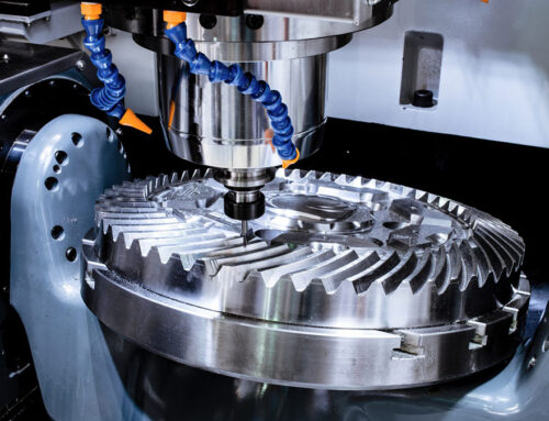
1.1 CNC Milling
The core of milling is “the tool rotates while the workpiece remains stationary”. CNC milling can process both flat and curved surfaces, as well as complex cavities. For instance, the arc shape of the laptop computer casing and the grooves in the mold are all processed through milling. There are three different types of milling machines: vertical, horizontal, and gantry.
Nearly 80% of the small and medium-sized parts in our workshop are processed using vertical machining centers (VMC), such as for making aluminum alloy brackets and small mold cores. The advantage is that it is convenient for clamping, and workers can clearly observe the cutting status while standing. The price is also moderate. However, attention should be paid to the load-bearing capacity of the worktable. If a lower load-bearing capacity is chosen to save costs, it may cause significant vibration, resulting in the surface of the processed parts not reaching the desired smoothness.
Horizontal machining centers (HMC) are suitable for processing box-type parts, such as engine cylinder blocks – one setup can process four surfaces, eliminating the need for repeated disassembly. But it takes up a lot of space and is about 30% more expensive than vertical machines. It is not cost-effective for small batch production. Generally, we recommend you to start considering it for a monthly production volume of higher than 500 pieces.
The last type is the gantry machining center. It is specifically used for processing large or heavy parts, such as the main shaft of wind power equipment and automotive body mold. For example, we previously helped a client process a 3-meter-long steel structure piece. Only the gantry machine’s frame can withstand the cutting force, and the worktable is large enough to accommodate the entire part in one setup. However, it has requirements for the height of the factory (at least 4 meters), and the cost is relatively high. Even the entry-level model costs tens of thousand dollars.
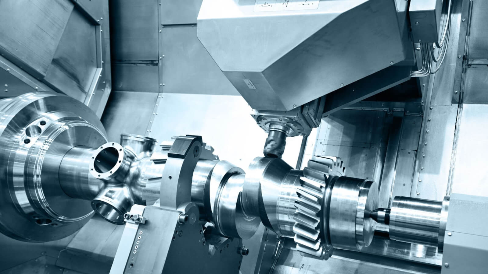
1.2 CNC Turning
The most fundamental difference between turning and milling lies in the fact that in turning, “the workpiece rotates while the tool remains stationary.”, which makes it particularly suitable for manufacturing circular parts, such as bolts, shafts, and flanges. Many people think that turning can only be used for simple external circles (ordinary CNC lathes), but we have upgraded the multi-functional turning center. Traditional ordinary CNC lathes are suitable for batch production of simple parts, such as optical shafts and nuts. They can machine dozens of pieces per minute, with high efficiency. However, they can only perform turning, and if you want to drill holes, you have to change the machine. The upgraded turning center has added a power tool turret and a C-axis. If you want to machine a stepped shaft with a hole, it can first machine the outer circle, then use the power tool turret to drill and thread, and finally use the C-axis to mill the side groove. All of this can be completed in one setup. This workload would require three processes if done with an ordinary lathe, but the turning center can do it in just one process, equivalent to a 60% increase in efficiency.
1.3 Grinding and Specialized Processing
Most of the processing can be accomplished through the aforementioned milling and turning. However, for some special requirements, special techniques are needed. To achieve a “mirror-like effect” surface for the parts, CNC grinding is required, such as for precision spindles and ball screws, CNC grinding can achieve a surface finish of Ra0.1 or lower which gives a mirror like feeling. Hard materials (such as quenched steel or ceramics) can only be finely processed through grinding. But it is inefficient, taking about 10-15 minutes to grind one part, and is usually used as the final process. CNC Wire Electrical Discharge Machining (Wire EDM) is used to deal with “complex dead corners”. For example, when making special holes for stamping molds, the milling cutter cannot reach them, so wire cutting is used – fast wire cutting is cheap but has average accuracy (±0.01mm), while slow wire cutting has high accuracy (±0.002mm), but the processing cost is 5 times higher. We use slow wire cutting for medical device micro parts. Electrical discharge machining is suitable for deep cavities in molds, such as complex grooves in injection molds. It uses copper electrodes to “burn” out the shape, which is more flexible than milling.
Above is subtractive processing. However, a recently popular additive + subtractive composite process is also gaining popularity. In recent years, many customers have asked if 3D printing can be used to make metal parts. But pure 3D printing has insufficient accuracy (and not to mention its high cost and relatively low efficiency), so we now commonly use an “additive + subtractive” composite machine: first, make a near-net-shape blank (such as the complex structure of aviation parts) using 3D printing (laser cladding), and then use CNC milling to finely process it to the required accuracy. When we made parts for an aviation accessory factory before, this method saved 60% of materials compared to pure subtractive processing, and complex structures could also be produced. Now this process is becoming increasingly popular in high-end manufacturing. However, because it incorporates 3D printing, the cost will also increase accordingly. And many factories do not have both 3D printing and CNC technologies at the same time, so coordinating projects across factories is also a problem. Therefore, we recommend that you choose a factory that has both technologies when doing such projects. A one-stop service provider like KingStar can solve these coordination problems that are difficult to handle.
2. Evaluate based on processing capability: Classified by “Number of Axes”
Many beginners believe that “the more axes, the better”, but in fact, in factories, the number of axes is “selected as needed” – adding one more axis makes the equipment cost 30,000 dollars or more. If the complexity of the project is not that high, there is no need to waste budget on the extra axis.
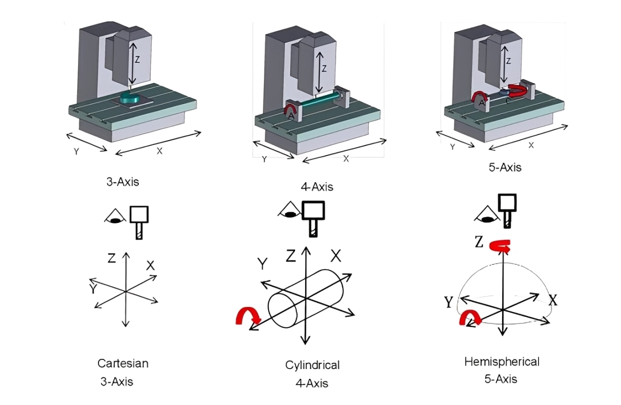
(Click to Enlarge)
2.1 3-Axis System
Firstly, there is the 3-axis system. The three axes are the X, Y, and Z linear axes, which can process the upper surface and sides of the parts, such as plates and simple cavities. Many newly-started customers ask us, “Should we directly go for five axes?” I always recommend trying the 3-axis system first: if the part does not have complex spatial surfaces (such as just a square with holes, simple arcs), the 3-axis system is completely sufficient, and the programming is simple, the equipment is cheap, and the maintenance cost is low.
2.2 4-axis system
The 4-axis system adds a rotation axis (usually the A axis, rotating around the X axis) to the 3-axis system. For example, to drill a slot on the side of a cylinder or drill a hole on a cone surface, the 4-axis system can handle it. Generally, if 3-axis system cannot handle your part, we recommend you to consider 4-axis system first rather than jump to 5-axis. Last year, a customer making valves had 4 inclined holes, using the 3-axis system required four clamping operations, with large errors, and after switching to the 4-axis system, the holes were drilled all at once, with a qualification rate from 80% to 99%. Moreover, the 4-axis system is half the cost of the 5-axis system, suitable for parts with “angle requirements” but no complex surfaces.
2.3 5-axis system
Next comes the most complex 5-axis system, which is the “top-of-the-line” for CNC, but there are two types:
3+2 axis positioning: technically speaking, it does not count for a “true” 5-axis system. It works like this: first, lock the two rotation axes to a specified angle and then use the three-axis for milling. For example, to drill a hole in a sloping surface, there is no need for complex fixtures, and the angle can be turned directly to drill. This cost is 30% lower than pure 5-axis and is very cost-effective for small and medium batch production. We often use it when making mold cavities for customers.
5-axis linkage: In this system, five axes move simultaneously. For example, processing a fan wheel or turbine blade – the tool needs to follow the curved surface and always maintain the optimal angle, otherwise it will over-cut. This is the “true” five-axis. This equipment is expensive (the entry-level model may cost for over $280,000 USD), the programming is complex, and it must be found experienced engineers (in our workshop, we require 5-axis operators to have over 8 years of experience). But for complex spatial surfaces, 5-axis linkage is the only choice, such as the blades of an aircraft engine, which can only be processed by it.
There is also a type of machine called turning-milling composite. Strictly speaking, it is not a new technique under the classification of the number of axes, but it is more “all-round” than the 5-axis system. It integrates the turning spindle and the milling power head, capable of doing both rotating bodies and special features. For example, making an axle with a gear, it can first turn the outer circle, then mill the gear, and finally drill the center hole, with the whole process done without changing the machine.
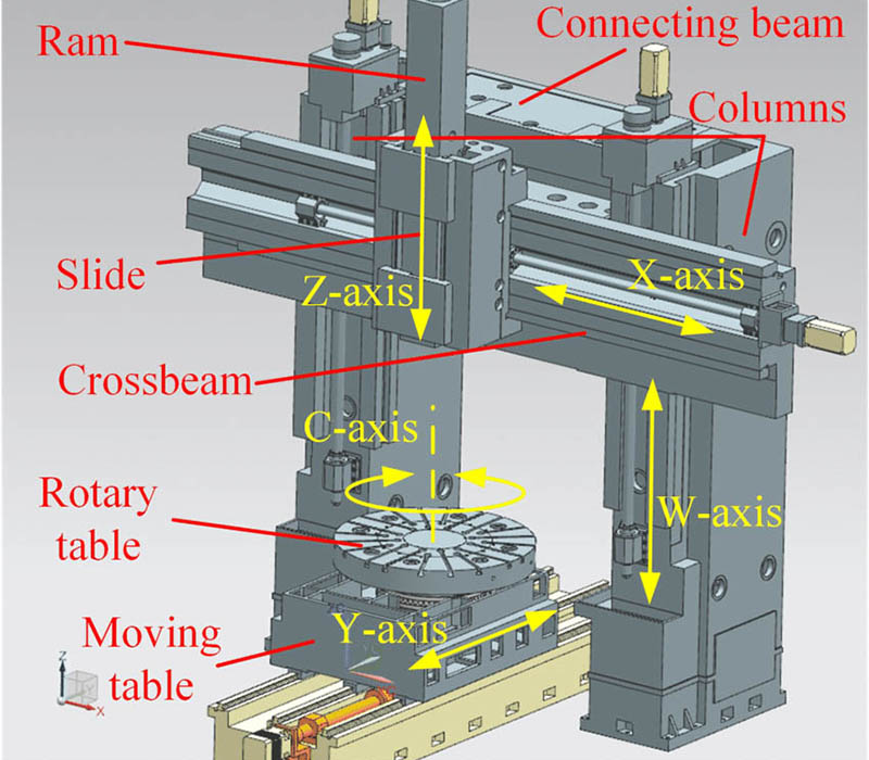
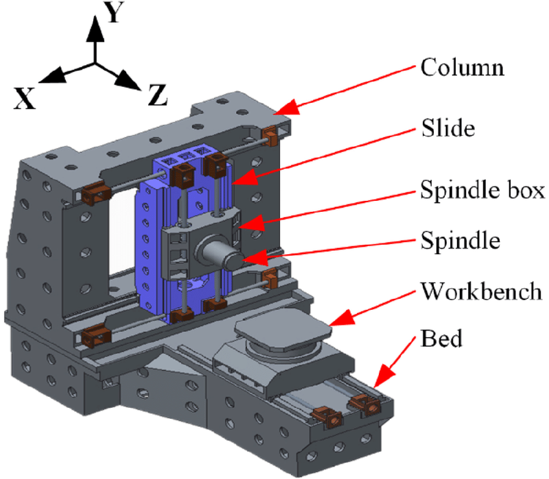
3. Final Implementation: Classified by “Machine Tool Layout” to suit your factory and production scenario
After choosing the process and the number of axes, you also need to consider whether the machine tool layout can fit into your factory and whether it can be compatible with your parts. The main classifications include vertical, horizontal and gantry types, along with a relatively special inverted layout. The vertical layout is also known as the C-type, taking up less space (2×3 m), suitable for small and medium-sized parts. It can be installed in factories with a height of 2.8 meters or above, making it the preferred choice for most small factories; the horizontal layout has a low center of gravity and convenient chip removal (chips fall directly), suitable for batch production of box-type parts, but it takes up a lot of space (3×4m), and a chip removal machine is required; the gantry layout: it requires a large factory space (at least 4m high and 5m wide), suitable for heavy and large parts, such as wind power and ship accessories. The inverted layout is relatively special, with the spindle at the bottom and the worktable at the top, suitable for batch production of disc-type parts (such as automotive brake discs), with convenient loading and unloading.
Vertical Machining Center
Horizontal Machining Center
4. Several Key Details to Consider for CNC Machining Project
- Wire cutting can only process through holes and cannot process blind holes (holes that do not extend to the bottom). When processing parts with a thickness exceeding 200mm, multiple cuts need to be considered in advance to ensure the perpendicularity.
- When choosing a CNC machine, in addition to positioning accuracy, it is necessary to additionally confirm the repeatability positioning accuracy, as it directly affects the consistency of part dimensions during mass production.
- Different CNC materials require matching corresponding tool materials: for processing hard materials such as stainless steel and titanium alloys, hard alloy tools are preferred; for processing soft materials such as aluminum and copper, high-speed steel tools can be selected to avoid rapid tool wear or low processing efficiency.
- During tapping processing, the rotational speed should be adjusted according to the material: for processing steel parts, the rotational speed should be controlled at 50-100r/min; for processing soft materials such as copper and aluminum, it can be appropriately increased to 100-200r/min to prevent tap breakage or substandard thread accuracy.
- Before multi-axis processing (4-axis / 5-axis), the accuracy of the tooling fixture needs to be calibrated to ensure that the coaxiality error between the fixture and the rotating axis is less than 0.005mm, to avoid parts being scrapped due to fixture offset.
- When grinding different materials, corresponding grinding wheels need to be replaced: for processing quenched steel, white corundum grinding wheels are used; for processing hard alloys, diamond grinding wheels are used. Mixing different grinding wheels will reduce surface finish or damage the grinding wheels.
- After programming is completed, a post-cutting simulation check needs to be performed, especially when processing complex curved surfaces and deep cavity parts, to carefully check whether the tool path has any interference with the non-machined surfaces of the part to avoid over-cutting phenomena.
5. Future Trends
Just like other industrial processes, CNC technology will continue to evolve towards the direction of intelligence and automation in the foreseeable future (even now). For instance, our machine tools are now equipped with sensors that can monitor the cutting force in real time. If the tool is worn, the system will automatically adjust the rotational speed and feed rate, preventing the failure of the parts due to a damaged tool. Moreover, with the development of unmanned production lines, many CNC monitoring and routine maintenance can now be accomplished by robots thus saving labor costs.
Another important trend is integration. As mentioned earlier, apart from additive + subtractive processes, there is now a “milling + grinding” integrated machine that can perform both rough and fine processing in one go, without the need to switch between different machines.
In fact, CNC classification is not a pure academic concept to memorize, but more of a solution for us to “match requirements” – when making the same part, different process choice may result in big variance in costs and efficiencies by even several times. If you have any confusion about part processing now: such as not knowing whether to use three-axis or four-axis, wanting to optimize the existing process to reduce costs, or wanting to understand how to set up an automated production line, you can contact us, the leading custom manufacturing company. We have engineers with 10+ years of experience who will conduct process analysis based on your part drawings (for free), and even conduct sample testing. Feel free to email us at sales@kingstarmold.com or leave online message.